Table of Contents
Advertisement
Quick Links
Advertisement
Table of Contents

Related Manuals for EverFocus ELR-4


Summary of Contents for EverFocus ELR-4
- Page 1 Instruction Manual...
- Page 2 All rights reserved. No part of the contents of this manual may be reproduced or transmitted in any form or by any means without written permission of the Everfocus Electronics Corporation. Release Date: Aug. 2009 QuickTime is a registered trademark of the Apple Computer, Inc.
- Page 3 Safety Precautions • To avoid any damage, please consider the following safety warnings: • Never place the recorder near to heaters, furnaces, other heat sources or under direct solar irradiation. • Operate the device only in locations providing the tolerable operating temperature range 0°C~40°C/32°F ~ +104°F.
- Page 4 WEEE This Product is RoHS compliant. The information in this manual was current upon publication. The manufacturer reserves the right to revise and improve his products. Therefore, all specifications are subject to change without prior notice. Misprints reserved. Please read this manual carefully before installing and using this unit. Be sure to keep it handy for later reference. iii iii iii iii...
-
Page 5: Table Of Contents
TABLE OF CONTENTS PRODUCT OVERVIEW ..................... 1 FEATURES ........................1 PACKAGE CONTENTS....................2 SPECIFICATIONS ......................3 FRONT PANEL ........................ 4 REAR PANEL........................6 INSTALLATION........................8 COVERT INSTALLATION ..................... 8 VIDEO INPUTS/OUTPUTS INSTALLATION ............. 10 AUDIO INSTALLATION ....................10 ALARM CONTACTS INSTALLATION ............... 10 2.4.1 Alarm Input Contacts ..........................11 2.4.2... - Page 6 LOGIN..........................24 SELECT CAMERA OPERATION................. 25 CHANGE AUDIO OUTPUT OPERATION ..............25 PLAYBACK........................25 PTZ ..........................27 4.6.1 General PTZ control ..........................27 4.6.2 Express control PTZ ..........................28 LAYOUT......................... 30 4.7.1 Bring to full screen mode ........................30 CHANNEL SWITCHING....................30 DISPLAY ........................31 4.10 SEQUENCE........................
- Page 7 Installing ActiveX controls ........................102 7.2.2 Enabling ActiveX Controls........................104 REMOTE LIVE VIEW ....................107 REMOTE PLAYBACK ....................108 EVERFOCUS DDNS SETUP ..................109 LINKSYS & D-LINK PORT FORWARDING ............. 110 LINKSYS PORT FORWARDING ................110 D-LINK PORT FORWARDING .................. 112 TROUBLESHOOTING ....................115 APPENDIX A: TIMING OF ALARM MODES..............
-
Page 8: Product Overview
DVR series. The ELR Series DVR comes with multiple control inputs. These inputs include mouse control, front panel control, IR remote control and EverFocus keyboard (EKB500) control. Mouse control is supported with the simple Graphical User Interface (GUI), offering experienced PC users the similarity of interactive command of a computer-controlled device. -
Page 9: Package Contents
1.2 PACKAGE CONTENTS Digital Video Recorder x1 User’s Manual Disk x1 AC Adapter and Power Cord x1 Hard Drive Rack Mount x1 SATA Connection Cable x1 Pack of screws x 1 * marked accessories not included in some models... -
Page 10: Specifications
Slim Type DVD Burner(Optional) User Interface GUI(Graphical User Interface) Embedded Linux Network/Protocol 10/100Mbps Ethernet; TCP-IP / DHCP/ PPPoE / Everfocus DDNS 1 USB 2.0 on Front Panel Schedule Setting Support Express and Advanced Schedule Setting User Access 3 Levels of User Access Support... -
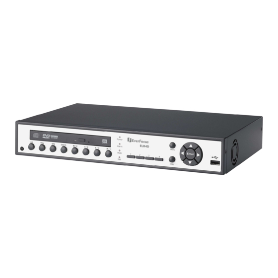
Page 11: Front Panel
1.4 FRONT PANEL Your primary interaction with your new DVR will be through the Front Panel buttons and their corresponding buttons on the included Remote Control. Take a moment to learn where the keys are as the remainder of the manual will refer to them often. Figure 1-1 Front Panel IR Receiver: Receiver for IR remote control... - Page 12 SEARCH: Press this key to enter Search Menu. For more detail about Search function, please see “4.12 Search ”. Fast reverse playback or step reverse playback depending on playback mode. ◄◄/◄I: ◄/ I I: Reverse playback or pause ►/ I I: Forward playback or pause Fast Forward playback or step forward playback depending on playback mode.
-
Page 13: Rear Panel
1.5 REAR PANEL During initial setup you will be connecting your DVR to multiple input and output devices. This is done through the rear panel. ○ ○ ○ ○ ○ ○ ○ ○ ○ ○ ○ Figure 1-2 Rear Panel ○... - Page 14 ○ ○ ○ ○ LAN: RJ-45 network connection...
-
Page 15: Installation
Chapter 2 INSTALLATION 2.1 COVERT INSTALLATION 1. Aim the small rectangular hole of the covert to the protrudent part of the front panel. Please see diagram 2.1. Diagram 2.1... - Page 16 2. Please see diagram 2.2 first. Make sure to have part 1 inserted inside the front panel, and part 2 has to stay outside the base. Finally, fix the covert firmly. Diagram 2.2...
-
Page 17: Video Inputs/Outputs Installation
2.2 VIDEO INPUTS/OUTPUTS INSTALLATION Camera and CCTV monitor must use 75 Ohm video cable (e.g. RG-59, RG-6, RG-11) with BNC connectors. Due to inappropriate absorbability, 50 Ohm coax cable (e.g. RG-58), antenna cable and other types of coaxial cable are not compatible. All connected video sources must provide a 1 Vpp NTSC or PAL standard video signal. -
Page 18: Alarm Input Contacts
2.4.1 Alarm Input Contacts ELR4 provides 4/8 alarm inputs. All inputs are programmable N.O. (Normal Open) or N.C. (Normal Closed) Inputs have to be switched by dry contacts. Alarm input with N.O. (Normal Open) contact Alarm input with N.C. (Normal Closed) contact in idle state in idle state All settings are programmed in the ALARM menu (chapter 5.5.1). -
Page 19: Alarm Output Relay
2. Record: The input switches to Record (or Record Standby) as long the contact is closed. CTRL IN CTRL IN Idle state Record / Record Standby 3. Armed / Disarmed: If the contact is closed, the DVR will switch off alarm (alarm contact and motion alarm) operation. - Page 20 Both the first and the last device in series should be terminated with 120 Ohm resistance in order to minimize line reflections. RS-485 bus serial wiring Cable length from box to device („Stubs“) has to be limited to 2m using connector boxes. RS-485 bus serial wiring with connector boxes and connection cable A direct RS-485 bus star wiring is not supported unless using a signal distributor (see below).
-
Page 21: Socket Pin Assignment
System expansion with RS-485 signal distributor ATTENTION: Most signal distributors are unidirectional! This means that the signal only flows from the input towards the outputs. Therefore, e.g. the interconnection of several keyboards is not possible with these types of signal distributor! 2.5.2 RS-485 socket pin assignment The following RS485 pin assignment as follow: 2.5.3 EKB-500 connection with network patch cable... -
Page 22: Usb-Mouse Installation
Supported protocols: EverFocus, Pelco-D, Pelco-P, Samsung, Transparent Required DVR settings: RS-485 receiver address in CAMERA menu chapter 5.3) RS-485 parameters and protocol in the I/O CONTROL menu chapter 5.10.4.) ATTENTION: Some Pelco-D / -P protocol domes and receivers require an address offset of -1, i.e. the... -
Page 23: Network Connection Through Patch Cable
Pinout of crossover-cable 2.7.2 Network Connection through Patch Cable The connection to an existing network requires a normal patch cable (straight-through). The illustration shows the connection to a network switch, router, or modem. Figure 2-2 Network Connection through Patch Cable Pinout of straight patchcable... -
Page 24: Final Install Process
2.8 FINAL INSTALL PROCESS Once you have completed the basic wiring connections, you are ready to turn on the DVR. Simply plug in the power source. The POWER LED will light up if power is normal. Once the system has finished loading, you can begin to set up the menu options for the DVR. -
Page 25: Mouse And Front Panel Operation
Chapter 3 MOUSE AND FRONT PANEL OPERATION ELR series DVR supports multiple sources to control the DVR. It can be controlled with a mouse, the front panel, an EKB500, the handheld remote control. This chapter will cover the basic operation using mouse and front panel. 3.1 GENERAL USB MOUSE OPERATION 3.1.1 How to select a channel / Enable audio 1. -
Page 26: Component Options
○ 1 ○ 2 ○ 3 Figure 3-2 OSD Menu ○ 1 In section 1, there are ten setup options available. Move the mouse over an icon and click to select it. ○ 2 In section 2, the categories for the selected icon will be displayed. Click on a word to select it. ○... - Page 27 * Note about on-screen keyboard: Click on a button to input that character. The buttons on the right and bottom have the following functions: Delete Delete the letter Done Confirm the selection All Caps Switch to capital letters Space Enter a space ←...
-
Page 28: General Front Panel Operation
3.2 GENERAL FRONT PANEL OPERATION 3.2.1 How to select a channel / Enable audio 1. In a view consisting of more than one channel, use the mouse or press arrow keys (Up/Down/Right/Left) to scroll through each channel that is displayed. The selected channel will be highlighted by white frame. -
Page 29: Component Options
○ 1 ○ 2 ○ 3 Figure 3-3 OSD Menu ○ 1 In section 1, there are ten setup options available. Use arrow keys to highlight an icon and press “Enter” to select it. ○ 2 In section 2, the main options for the selected icon will be displayed. Use Up/Down arrow keys to highlight an option and press “Enter”... - Page 30 Bar: Press “Enter” key to activate the slider, then use arrow keys to adjust the setting. Press “Enter” again to finalize the changes.
-
Page 31: General Dvr Operations
Chapter 4 GENERAL DVR OPERATIONS This chapter introduces the operations on major functions including playback, layout change, sequence, triplex operations, copy, and search. 4.1 RECORD By default, the ELR series DVR will always be in record mode. When the DVR is turned on, it will start to record. -
Page 32: Select Camera Operation
+ To input password by mouse: click the password field to bring up the on-screen keyboard (see Figure 4-2 On-screen Keyboard). Click on each button to input the desired characters for the password. When finished, click “Done” on the on-screen keyboard to confirm the password. + To input password using front panel: press “Enter”... - Page 33 To playback: By mouse: Right-click to bring up the menu bar and click on to enter Playback Menu. By front panel: Press key to enter Playback Setup Menu. A playback bar will show as the figure below: 1 2 3 4 10 11 13 12 10 10 5 6 7 8...
-
Page 34: Ptz
Click “Delete” button 9. Steps to run Auto Pan a. Click “Auto Pan” button 10. Pattern Operation (Pattern is the “0” Tour in Everfocus and Pelco PTZ cameras) a. Click “Pattern” button 11. Steps to run a tour a. Click “Tour” button b. -
Page 35: Express Control Ptz
b. Click the number of the desired tour c. Click “Delete” button Click “C” to clear the digit in cell Click “X” at top-right corner to close PTZ menu. Click “Exit” to leave PTZ function. 4.6.2 Express control PTZ When PTZ menu is closed, the mouse cursor will change to a different icon in different areas of the screen. User can control PTZ direction, zoom, and focus by clicking directly on screen. - Page 36 • 7: Zoom in • 11: Zoom out...
-
Page 37: Layout
4.7 LAYOUT The ELR DVR has a total of four display modes available. The different available layouts are shown below: (9 screens) (4 screens) (PIP) (Full) NOTE: PIP display is not available in Playback mode To change layout, follow the steps below: By mouse: Right-click to bring up the menu bar and click to scroll through each display option. -
Page 38: Display
4.9 DISPLAY 1. Press Display button on menu by using mouse or press “Display” button on the front panel. 2. Press once to show camera information. Please see the following table for status representation. Recording Playback Fast forward Fast backward Back pause Alarm... -
Page 39: Search
4. When in ZOOM mode, the mouse cursor will change to a different icon in different areas of the screen. User can control PTZ direction, zoom, and focus by clicking directly on screen: Figure 4-4 Zoom Express Control The screen is divided into a 4x4 grid. The function of each section is defined as below: •... -
Page 40: Time Search
4.12.1 Time Search Figure 4-5 Search Menu – Time Search Play From: Select the time to be searched by choosing the Date and Time. Click on the “Play” button to start search. The DVR will automatically play the video being searched. DVR will play the nearest time if there is no data in selected time. -
Page 41: Event Search
4.12.2 Event Search Figure 4-6 Search Menu – Event Search From: Select starting date and time To: Select ending date and time. Camera: Select which cameras to search for. Event: Select which event type(s) to search for. Choose from Alarm, Motion, Video Loss, or Others. Click on the “Search”... - Page 42 Prev Page: Go to previous page Next Page: Go to next page Unlock: Unlock the item if the item is locked Lock: Lock the item (After click Lock button, the selected item will show Locked or Partial) Delete: Delete item if it is not locked Play: Playback selected item Copy: Copy selected item In Lock status, there will show “Partial”...
-
Page 43: Copy
4.13 COPY To bring up Copy menu: By mouse: Right-click to bring up the menu bar and click on to enter Copy Menu. By front panel: Press “Copy” key to enter Copy Menu directly. Figure 4-7 Copy Menu Camera: Select which camera will be archived. Choose “Select All” to select all the cameras. Player: Check the box to include the ePlayer program as part of the copy. -
Page 44: Logout
4.14 LOGOUT Right-click to bring up the menu bar and click button to bring up the Logout Confirmation window (see Figure 4-8). Figure 4-8 Logout Confirmation window Press “Yes” button when you are ready to logout from the system. You will need to login again before accessing any other options. -
Page 45: Dvr Configuration
Chapter 5 DVR CONFIGURATION This chapter will walk you through the DVR Menu Settings step by step and show you how to set the DVR for your specific application. 5.1 CONFIGURATION MENU 1. To bring up the Main Menu, press the “Menu” key on the front panel or right-click with the USB mouse to bring up the OSD menu bar. - Page 46 Date: Set the current date of DVR. Time: Set the current time of DVR. Record Mode: Normal+Event: Normal recording plus event recording. Event Only: Event recording only. Schedule Rec: Schedule recording. Enter the number of hours per day for the estimate event. Resolution: Select recording resolution based on video format.
-
Page 47: Camera Setting
Network Type: Fixed IP: User can set a fixed IP for network connection. DHCP: DHCP server in LAN will automatically assign IP for network connection. PPPoE: This is a DSL connection application ONLY. Check with your ISP if they use PPPoE. IP Address: This field shows the current IP Address for the DVR. -
Page 48: Basic Setting
Figure 5-2 Camera Menu-Basic Setting 5.3.1 Basic Setting Camera: Select the camera number. Title: The title setting allows you to assign a title to selected camera. Each title supports up to 16 characters. The on-screen keyboard will appear when you click the title option. Install: Check the box to enable the current camera. - Page 49 Resolution: Select recording resolution based on video format. NTSC: 720x480 / 720x240 / 360x240 PAL: 720x576 / 720x288 / 360x288 Record Quality: Select an image quality for recording. There are five different qualities available: Superior, High, Standard, Basic and Low. A higher image quality uses more HDD space. Normal Speed: Frame rate in images per second (IPS) for continuous recording.
-
Page 50: Video Adjust
5.3.2 Video Adjust Figure 5-3 Camera Menu – Video Adjust Camera: Select the camera you wish to adjust. “Title” will change to the name of the selected camera. Brightness: Adjusts how bright/dark the picture appears. If details appear to be lost in the shadows or darker regions, try increasing the Brightness. -
Page 51: Motion
5.3.3 Motion Figure 5-4 Camera Menu – Motion Camera: Select the camera you wish to adjust. “Title” will change to the title name of the selected camera. Enable: Check box to enable motion detection. Other motion options will not be available unless this feature is selected. - Page 52 Permanent: Alarm will remain on until user presses “Enter” key on front panel. Timeout Duration: Time duration selectable from 1 to 150 seconds. Edit Motion Grid: Press this button to edit the motion grid (See Figure 5-5 Camera Menu – Motion Grid Setting ).
-
Page 54: Video Loss
5.3.4 Video Loss Figure 5-6 Camera Menu – Video Loss Camera: Select the camera you wish to adjust, “Title” will change to the title name of the selected camera. Enable: Check box to enable Video Loss. Log: Check box to record video loss events in the log. Pre-alarm Record: Check box to record several moments before the video loss. -
Page 55: Record & Play Setting
Apply To: This button can be used to copy the video loss settings to other cameras. Select which cameras you wish to copy to. "Select All" selects all cameras, “Unselect All” deselects all cameras. Click “OK” to copy the settings or "Cancel" to exit without copying. 5.4 RECORD &... -
Page 56: Built-In Cal
Schedule Record: Use schedule recording mode. For Schedule recording, the only way to stop schedule recording is to turn schedule recording off. Pressing any keypad on front panel to change schedule recording will not work during scheduling record mode. When schedule recording is disabled, DVR will auto turn on recording. Time Stamp: Select if the time and date will display while recording. -
Page 57: Play
5.4.3 Play Figure 5-9 Record & Play Menu - Play Quick Playback: Check the box to enable quick playback function. Playback From X Seconds ago: When the DVR is put into playback, it will begin playing from the selected time. Choose from 60 to 3600 seconds. -
Page 58: Alarm & Event Setting
5.5 ALARM & EVENT SETTING Figure 5-10 is a screen shot of the ALARM & EVENT SETTING MENU. This menu will walk you through alarm and event setup. Figure 5-10 Alarm & Event Menu - Alarm 5.5.1 Alarm Alarm: Select the alarm number from 1 to 4. Enable: Check box to enable alarm. - Page 59 N.C.: Normal Close contact. Network Alarm: Check box to send out a network alarm to client PC when motion occurs. (requires PowerCon software and setting up Alarm Server in Network Setup menu) Active Camera: This field is for assigning the alarm to a specific camera. For example if you had an external motion detector on camera one you would set this option to “1”.
-
Page 60: Event
5.5.2 Event This section covers internal system event warnings. Figure 5-11 Alarm & Event Menu – Event Event: Select from the following event types. HD Temperature: Hard drive is over the safety warning temperature HD Failure: If DVR fails to detect a HDD on start up, the system will create a HD failure event. HD Full: If the DVR is not set to Overwrite in the Record Menu, an event will be created when all HDDs are filled. - Page 61 HD Temperature: Figure 5-12 Alarm & Event Menu – Event - HD Temperature Log: Check box to record events in the log. Buzzer: Check box to enable buzzer when hard drive’s temperature is over the “Temp. Warning Limit”. Email Notify: Check box to enable email notification when temperature is over the “Temp. Warning Limit”. Network Alarm: Check box to send out a network alarm to client PC.
- Page 62 HD Failure: Figure 5-13 Alarm & Event Menu – Event - HD Failure Log: Check box to record events in the log. Buzzer: Check box to enable buzzer when no hard drive is detected. Email Notify: Check box to enable email notification function when HD fails. Network Alarm: Check box to send out a network alarm to client PC.
- Page 63 HD Full: Figure 5-14 Alarm & Event Menu – Event - HD Full Log: Check box to record events in the log. Buzzer: Check box to enable buzzer when hard drive is full. Email Notify: Check box to enable email notification when HD is full. Network Alarm: Check box to send out a network alarm to client PC.
- Page 64 HD Off: Figure 5-15 Alarm & Event Menu – Event - HD Off Buzzer: Check box to enable buzzer when hard drive is off. Email Notify: Check box to enable email notification when HD is off. Network Alarm: Check box to send out a network alarm to client PC. (requires PowerCon software and setting up Alarm Server in Network Setup menu) Alarm Output: This will transmit a signal through one of the alarm outputs.
- Page 65 Power Loss: Figure 5-16 Alarm & Event Menu – Event – Power Loss Log: Log is permanently checked for this feature. Power Loss events are always recorded by the DVR. Email Notify: Check box to enable email notification when HD is off. Network Alarm: Check box to send out a network alarm to client PC.
- Page 66 Network Loss: Figure 5-17 Alarm & Event Menu – Event – Network Loss Log: Check box to record events in the log. Buzzer: Check box to enable buzzer when network is lost. Alarm Output: This will transmit a signal through one of the alarm outputs. It can be set to either “NONE” (not active) or “1”.
-
Page 67: Schedule Setting
5.6 SCHEDULE SETTING Figure 5-18 is a screen shot of the SCHEDULE SETTING MENU. In this menu you can set a unique timer to start recording during a specified time period. This menu is used to configure Express Setup, Holidays and Schedule settings. -
Page 68: Holidays
Event Frame Rate: FPS recording rate for events. Selectable frame rate includes 30fps, 15fps, 10fps, 7.5fps, 5fps, 1fps or 0fps. Event Action: Check this box to enable Buzzer, Alarm out, E-mail and Network actions when an event occurs on the selected time period. Apply: Press “Apply”... -
Page 69: Schedule
One time: Records date only once. Month/date: Repeats recording on the same specific date. Month/weekday: Repeats recording on a specific day of the month/week. Details: Specifies the date to be recorded. Prev: Previous Page (30 Holidays Total) Next: Next Page (30 Holidays Total) 5.6.3 Schedule Figure 5-20 Schedule Menu-Schedule Camera: Select a number to change the schedule for that camera. - Page 70 To Set Schedule using Mouse 1. Click on desired start time block (no numbers on it) on a time bar. At this time, the selected block will be highlighted in blue frame and the selected time bar will be highlighted by red frame. There are 24 blocks on the time bar representing 24 hours respectively.
- Page 71 3. Selecting camera: Use Right/Left arrow key to select desired camera to configure. Selected camera number will be highlighted by a blue frame. See above image. 4. Enter time bar editing mode: Use Up/Down arrow key to switch to time bar editing mode. When this mode is selected, all 9 time bars will be highlighted within a blue frame.
- Page 72 7. Changing recording mode (color) of a timezone: Use Right/Left arrow key to switch to the first block (with number on it) of a timezone. Clicking Enter button, and this timezone will switch to another color, which means switching to another record mode. The color switch sequence is gray->orange->blue. Press “Edit Timezone”...
- Page 73 NTSC: 720x480; 720x240; 360x240 PAL: 720x576 / 720x288 / 360x288 Normal: Frame rate in images per second for continuous recording. The speed is limited to the maximum recording rate of the DVR divided by the number of installed cameras. Event: Frame rate in images per second for event recording. Event record speed can be set from 1 to 30 (25 for PAL).
-
Page 74: Alarm Action
5.6.4 Alarm Action Alarm: Select a number to change the schedule for that alarm. Each alarm can be set on a 24 hour time block for Holiday (Hol), Other (Oth), Sunday (Sun), Monday (Mon), Tuesday (Tue), Wednesday (Wed), Thursday (Thu), Friday (Fri), or Saturday (Sat). Time Bar: The time bar uses two different colors to distinguish each recoding mode. - Page 75 Repeat clicking on the first block (with number on it) of any timezone, this timezone will change from one color to another, which means switching the record mode. The color switch sequence is gray->orange. Alarm Action Setting from front panel Enter Alarm Action setting mode: press “Enter”...
- Page 76 Editing blocks in a time bar: when a time bar is selected (highlighted in red frame), press Enter button, then the first block of this bar will be selected (highlighted in blue frame). Use Right/Left arrow key to switch to desired block as starting time, and press Enter button again to confirm. At this time, the current and all following blocks will turn into gray, which means this gray timezone has been set to the recording mode of gray (Alarm Action off).
- Page 77 Apply to Cameras: This button can be used to copy schedules to other cameras. Select which cameras you wish to copy to. "Select All" selects all cameras, “Clear All” deselects all cameras. Click “OK” to copy the settings or "Cancel" to exit without copying.
-
Page 78: Network Setting
5.7 NETWORK SETTING Figure 5-22 is a screen shot of the NETWORK SETTING MENU. This menu is for configuring the DVR for a network connection. NOTE: Since every Network Configuration is different, please check with your Network Administrator or ISP to see if your DVR requires specific IP addresses and/or port numbers. -
Page 79: Email
DNS Server 2: This field shows the secondary DNS server for your network. HTTP Port: Port number for HTTP/WEB communication. 5.7.2 EMAIL Figure 5-23 Network Menu – Email SMTP Server: Assign the SMTP (e-mail) server’s name. NOTE: For more reliable email service, use the server’s IP address. SMTP Port: Assign the port number used by the SMTP server. -
Page 80: Ddns
DDNS Server: Select either “EverfocusDDNS” or “www.dyndns.org” as the DDNS provider. If DDNS will not be used, simply select “Disable”. EverfocusDDNS Figure 5-24 EverfocusDDNS DVR Name: Input the desired name for the DVR Register/Update: Click the button to submit and register the name to the Everfocus server. - Page 81 Host name: Host name created through the dyndns account. User name: User name of the dyndns account. Password: Password of the dyndns account. Confirm: Re-enter password. Note: For more details on DDNS setup, please see “Chapter 8 - Everfocus DDNS Setup”.
-
Page 82: Alarm Server
5.7.4 Alarm Server Figure 5-26 Network Menu – Alarm Server Server IP1~3: IP address of client PC with installed PowerCon Software. The network alarm can be transmitted to up to 3 addresses. Protocol: Select the protocol type for alarm transmission: UDP: User Datagram Protocol TCP: Transmission Control Protocol Port: Select the transmission port for network alarm messages... -
Page 83: Disk Setting
5.8 Disk Setting 5-27 is a screen shot of the DISK SETTING MENU. This menu is used to review and manage the DVR’s hard drive settings. Figure 5-27 Disk Menu 5.8.1 Disk Record Time (Start): Shows earliest recorded time on the hard drive. Record Time (End): Shows latest or most current recorded time on the hard drive. -
Page 84: Display Setting
5.9 DISPLAY SETTING Figure 5-28 is a screen shot of the DISPLAY SETTING MENU. This menu will walk you through Monitor On-Screen Display (OSD) and Sequential setup. Figure 5-28 Display Menu – Monitor OSD 5.9.1 Monitor OSD These are the display options for the Main Monitor. Main Monitor Camera Title: Check the box to display camera titles. -
Page 85: Main M/T Seq
5.9.2 Main M/T SEQ Figure 5-29 Display Menu – Main M/T SEQ Step: Sequence order. Cannot be changed. Camera: Select which camera appears on the current step. Dwell (sec): Set the dwell time for each step. Sequence dwell time can be set from 0 to 99 seconds. -
Page 86: System Setting
5.10 SYSTEM SETTING Figure 5-30 is a screen shot of the SYSTEM SETTING MENU. This menu is for setting up the system configurations of the DVR. Figure 5-30 System Menu – Date/Time 5.10.1 Date/Time Date: Set current Date. Time: Set current Time. Date Format: Choose date format from yyyy/mm/dd, dd/mm/yyyy, and mm/dd/yyyy. -
Page 87: Daylight Saving
5.10.2 Daylight Saving Figure 5-31 System Menu – Daylight Saving Daylight Saving: Check the box to enable daylight saving time. Start Date: Set the start date of daylight saving time. Start Time (hh:mm): Set the time when daylight saving time begins. Set To (hh:mm): This is what the time will change to when daylight saving begins. -
Page 88: User
5.10.3 User User Menu is where you can add or delete different users on the system as well as set administrator rights. Figure 5-32 System Menu – User Click “Add” button to add a new user. Set the name (case-sensitive), password, and access level. Press “Add”... - Page 89 Edit Click “Edit” button to make changes to an existing user account. Press “Save” button to save changes or “Cancel” to exit without making changes. Figure 5-34 System Menu – User - Edit User Login: Check this box to activate user login. When this is disabled, no username or password is required to access the system, and all users operate with ADMIN rights.
-
Page 90: I/O Control
PTZ Protocol: Select PTZ protocol, choose from the following protocols: Transparent, Pelco D, Pelco P, Everfocus, or Samsung. (NOTE: all cameras must be on the same protocol) 485 ID: If more than one DVR is used through the RS485 connection, each one must be assigned a unique ID number between 0 and 127. -
Page 91: Misc
5.10.5 Misc. Figure 5-36 System Menu – Firmware & Misc. Firmware Current Firmware Version: Displays the current version. Firmware Upgrade: Press “Upgrade” to upgrade the firmware. NOTE: To perform a Firmware Upgrade, you will need to connect a USB flash device with the latest version of the firmware. -
Page 92: Information Setting
5.11 INFORMATION SETTING 5.37 is a screen shot of the INFORMATION SETTING MENU. This menu displays important system information. Figure 5-37 Information Menu – System. 5.11.1 System System Version: Displays firmware version number. Model: Displays DVR model number. NTSC/PAL: Displays current video format. Network IP: Displays the DVR’s current IP Address. -
Page 93: Log
5.11.2 Log Figure 5-38 Information Menu – Log From Date: Select starting date of log to be displayed. Time: Select starting time of log to be displayed. Date: Select end date of log to be displayed. Time: Select end time of log to be displayed. Log Type: Configurations: to see log sorted by configurations. - Page 94 Figure 5-39 Log List Prev Page: Go to the previous page of log. Next Page: Go to the next page of log. Close: Close the window...
-
Page 95: Networking Overview
Chapter 6 Networking Overview This chapter will give you a basic instruction on how to set up the DVR for network connection. It is highly recommended that you have a working knowledge of what a network is and how it works. This will be helpful in completing the networking process. -
Page 96: Virtual Ports
There are many types of high speed Internet available. The most common ones are T1, Cable, and DSL (in order of speed). The DVR is not compatible with a dial-up connection. Note: EverFocus suggests having a minimum upload speed of 256KBps. This can be addressed by your Internet Service Provider. -
Page 97: What Is Your Network Setup
This makes it much simpler to host a website, email server, or other type of server connection. Everfocus suggests using a static IP address. If this is not available, you will need to use a dynamic IP address. This is explained below. -
Page 98: Simple One To One Connection
Once you have a cross-over cable plug one end into the LAN port on the back of the DVR and the other into the network card on the back of the computer. Log into the EverFocus DVR menu and go to the Network Setting Menu. You must use the Static IP option for this type of connection. - Page 99 Assign an IP of 192.168.001.003, a Subnet Mask of 255.255.255.000, and a Gateway of 192.168.001.001. You can ignore DNS Server. The next step is to set the computer’s network settings to match those of the DVR. You will need Administrator privileges on your Windows machine to do this. To assign a fixed IP address in Windows 2000/XP.
- Page 102 Click on the option that says “Use the following IP address” Assign an IP address of 192.168.1.2, a Subnet Mask of 255.255.255.0, and a Default Gateway of 192.168.1.1, then click OK. Restart both the computer and the DVR. To access the DVR from the computer, simply open Internet Explorer and in the address bar type: http://192.168.1.3...
-
Page 103: Direct High Speed Modem Connection
Once you have a straight through cable plug one end into the LAN port on the back of the recorder and the other into the high speed modem. Log into the EverFocus DVR menu and go to the Network Setting Menu. Input the Static IP address, the Subnet Mask, and the Gateway that you obtained from the internet... - Page 104 Note: If you have a dynamic IP address, you can set the DVR to DHCP to automatically detect the network settings settings. Therefore, it can use a dynamic IP address. Exit from the DVR’s Menu to save the settings. To access the DVR from a computer, open Internet Explorer and in the address bar type: http:// (IP address given by your internet service provider) Note: When using this type of connection, only one device can be connected to the modem at a time.
-
Page 105: Router Or Lan Connection
6.9 Router or LAN Connection Straight Through Ethernet Cable Pin outs: The Figure below shows the pin configurations for a straight cable. Connection Procedure: The First step is to purchase or make a straight through cable. We recommend purchasing one if you have never made a straight through cable. - Page 106 Once you have a straight through cable plug one end into the LAN port on the back of the recorder and the other into the router. Log into the EverFocus DVR menu and go to the Network Setting Menu. To let the router automatically assign an address: Set the Network Type to DHCP.
- Page 107 number of the IP address. For example, if the IP address of the computer is 192.168.2.101, the DVR’s IP address should be 192.168.002.050. To access the DVR from a computer simply open Internet Explorer and in the address bar type: http:// (IP address of the DVR) Note: The DVR’s IP address will only work at the location of the DVR.
-
Page 108: Remote Operation From Browser
Chapter 7 REMOTE OPERATION FROM BROWSER 7.1 CONNECTING TO ELR To access the DVR from a computer, open an Internet Explorer window and in the address bar type: Local connection: http:// (IP address from the DVR’s Network Menu) Internet connection: http:// (IP address given by your Internet Service Provider) The login page will appear on the screen similar to the one shown above. -
Page 109: Browser Security Setting
7.2 BROWSER SECURITY SETTING 7.2.1 Installing ActiveX controls When you first connect to the DVR’s IP address, you should see a screen like the one below. If you do not see a yellow bar like the one the arrow is pointing at, your security settings may be too high. If so, go to “Section 7.2.2 - Enabling ActiveX Controls.”... - Page 110 Install the ePlusDVR.cab file when prompted to do so. Once the file finishes installing, you will return to the same login page as before. Type in the username and password and click Login to view the cameras. Default username: admin Default password: 11111111...
-
Page 111: Enabling Activex Controls
7.2.2 Enabling ActiveX Controls Note: This section is only necessary if you DO NOT see the yellow ActiveX bar at the top of your browser screen when you first connect to the DVR. At the top of the Internet Explorer Window, click on Tools, then select Internet Options. Click the Security tab at the top of the window, then choose Custom Level near the bottom. - Page 112 In the Security Settings window, scroll to “ActiveX controls and plug-ins” Set the controls as follows: “Enable”: Allow previously unused ActiveX controls to run without prompt (Internet Explorer 7 only) Allow scriptlets (IE7 only) Automatic prompting for ActiveX controls Binary and script behaviors Display video and animation on a webpage that does not use external media player (IE7 only) Run ActiveX controls and plug-ins Script ActiveX controls marked safe for scripting...
- Page 113 Close the window so you are back at the login screen. Click the Refresh button to reload the page. Install the ePlusDVR.cab file when prompted to do so. Once the file finishes installing, you will return to the same login page as before. Type in the user name and password and click Login to view the cameras.
-
Page 114: Remote Live View
7.3 REMOTE LIVE VIEW 1. In the main page, you will see live images in a 4-screen display (or 8 screens, depending on the model). 2. The status of each camera is represented by different colors on the left side of the screen. Green means normal;... -
Page 115: Remote Playback
7.4 REMOTE PLAYBACK To playback the video, press “Search” button. Select from “Time Search”, “Event Search”, or “Motion Search”. For more details about Search setting, please refer to “4.12 Search Setting”. “Event Search” and “Motion Search” will show maximum 400 search result items (near start time) Playback Control Keys Playback Control Keys: Fast rewind the video. -
Page 116: Everfocus Ddns Setup
Chapter 8 EVERFOCUS DDNS SETUP Setup Steps: Step 1. Set up the Network Menu according to the instructions detailed in the Networking chapter. (Make sure that DNS Server 1 is set correctly or DDNS will not work) Step 2. Go to the website http://everfocusddns.com... -
Page 117: Linksys & D-Link Port Forwarding
Chapter 9 LINKSYS & D-LINK PORT FORWARDING 9.1 LINKSYS PORT FORWARDING This section will cover a few simple configurations for the Linksys router. This chapter is only to offer some help to the installer and end user. Please understand we DO NOT support this product and will not give tech support on it. - Page 118 Applications and Gaming allows you to set up public services on your network, such as web servers, ftp servers, e-mail servers, or other specialized Internet applications. (Some Internet applications may not require any forwarding) To forward a port, enter the information on each line for the criteria required. Descriptions of each criterion are described here.
-
Page 119: D-Link Port Forwarding
9.2 D-LINK PORT FORWARDING This section will cover a few simple configurations for the D-Link router. This chapter is only to offer some help to the installer and end user. Please understand we DO NOT support this product and will not give tech support on it. - Page 120 Click Virtual Servers on the left to bring up the following screen. Virtual Servers allows users who are connecting remotely to access services on the router’s Local Network. The functions of each field are described below. Virtual Server - Select Enabled or Disabled Name - Enter the name referencing the virtual service Private IP - The IP address of the device running the local services.
- Page 121 Here is an example of the information for each service: Name Private IP Protocol Private Port Public Port Schedule HTTP 192.168.1.50 Both Enable CTRL 192.168.1.50 Both 1600 1600 Enable Note: If you changed port 80 in the DVR’s Network Menu, open that port instead of 80.
-
Page 122: Troubleshooting
Chapter 10 TROUBLESHOOTING If you have problems with the system, run through the following checklist to see if you can solve the problem. The DVR will not go into record mode. Bring up the DVR’s Menu and check under the Camera Menu. Verify that all connected cameras are checked as “Installed”... -
Page 123: Appendix A: Timing Of Alarm Modes
Appendix APPENDIX A: TIMING OF ALARM MODES Transparent Mode Input Event Alarm Duration Event = Reaction Duration of alarm input source (motion, contact, system events...) Event Resulting duration for this alarm mode, related to event record, alarm outputs, OSD message, reaction buzzer Timeout + Transparent Mode... - Page 124 Timeout Mode Input Event Alarm Duration Event Duration = Reaction Duration of alarm input source (motion, contact, system events...) Event Alarm duration for timeout, defined in the event setup menus Duration Resulting duration for this alarm mode, related to event record, alarm outputs, OSD message, reaction buzzer Permanent Mode...
- Page 125 Timeout Mode: Retrigger of Alarms Duration of alarm input source (motion, contact, system events...) Event Alarm duration for timeout, defined in the event setup menus Duration Resulting duration for this alarm mode, related to event record, alarm outputs, OSD message, reaction buzzer Timeout+Transparent Mode: Retrigger of Alarms...
-
Page 126: Appendix B: Changing Rule For Express Setup
Appendix APPENDIX B: CHANGING RULE FOR EXPRESS SETUP Case 1: Record Mode: Normal + Event Record With: Recording days DVR will Auto adjust Quality and Event frame rate to match the Recording days which user selected: According to resolution, event hours and assumption above, DVR will select one set of suitable quality and event frame rate from Changing Order 1 to 8. - Page 127 Case 3: Record Mode: Normal + Event or Event Only Record With: Preset Setting DVR will apply setting in below table to all cameras according to different Preset Setting. Preset Setting Option Camera Item Apply value Quality Superior Best Quality Normal Frame Rate Max recording frame rate of DVR Event Frame Rate Quality...
- Page 128 Tel: +1-626-844-8888 Sales: +1-631-436-5070 Fax: +1-626-844-8838 Fax: +1-631-436-5027 Ihr EverFocus Produkt wurde Your EverFocus product is designed entwickelt und hergestellt mit qualitativ and manufactured with high quality hochwertigen Materialien und materials and components which can Komponenten, die recycelt und wieder be recycled and reused.
Need help?
Do you have a question about the ELR-4 and is the answer not in the manual?
Questions and answers