Table of Contents
Advertisement
Quick Links
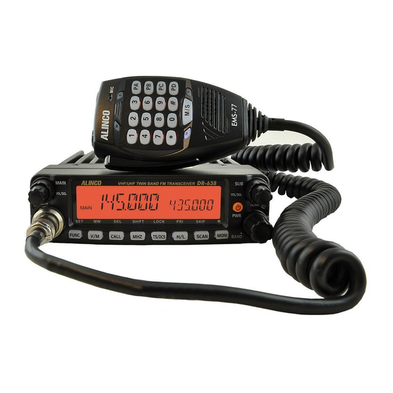
VHF/UHF FM Mobile Transceiver
DR-638
Instruction Manual
Thank you for purchasing your new Alinco transceiver.
Please read this manual carefully before using the
product to ensure full performance, and keep this
manual for future reference as it contains information
on after-sales services. In case addendum or errata
sheets are included with this product, please read
those materials and keep them together with this
instruction manual for future reference.
NOTE: DR-638 may be delivered to you after dealer-
programming. In such cases, please ask your dealer about
the available features in your unit and how to operate this unit.
Features and functions may be limited due to dealer-
programming.
Advertisement
Table of Contents

Subscribe to Our Youtube Channel
Related Manuals for Alinco DR-638


Summary of Contents for Alinco DR-638
- Page 1 NOTE: DR-638 may be delivered to you after dealer- programming. In such cases, please ask your dealer about the available features in your unit and how to operate this unit.
- Page 2 ALINCO, INC. Y odoyabashi Dai-bldg 13F 4-4-9 Koraibashi, Chuo-ku, Osaka 541-0043 Japan Phone: +81-6-7636-2362 Fax: +81-6-6208-3802 http://www.alinco.com E-mail:export@alinco.co.jp Copyright Alinco, lnc. PS0819/FNEH-NI Printed in China...
- Page 3 Copyright 2012 All rights reserved. NO part of this document may be of the function. reproduced, copied, translated or transcribed in any form or by any means without the prior writhout the prior written permission of Alinco. Inc, Osaka, Japan, English Edition Printed in China. Before transmitting There are many radio stations operating in proximity to the frequency ranges this product covers.
- Page 4 All brand names and trademarks are the property of their that users learn how to operate the units directly from the dealer who respective owners. Alinco cannot be liable for pictorial or typographical programmed the functions and channels. Please contact the dealer for inaccuracies.
- Page 5 radio by the manufacturer or an antenna specifically authorized by the INFORMATION SAFETY TRAINING manufacturer for use with this radio. Land-mobile version only • DO NOT transmit for more than 50% during the time of employment WARNING: (50% duty cycle or less). Transmitting excessive amount of time can This radio generates RF electromagnetic energy during transmission.
- Page 6 FCC INFORMATION / LAND-MOBILE VERSION ONLY FOR CLASS B UNINTENTIONAL RADIATORS: This equipment has been tested and found to comply with the limits for a Class B digital device, pursuant to part 15 of the FCC Rules. These limits are designed to provide reasonable protection against harmful interference in a residential installation.
- Page 7 WARNING To prevent any hazard during operation of Alinco’s radio product, in this Do not use this product in close proximity to other electronics manual and on the product you may find symbols shown below. Please devices, especially medical ones. It may cause interference read and understand the meanings of these symbols before starting to to those devices.
- Page 8 WARNING Handling this product: Do not plug the power-supply into the wall outlet if the contacts are dirty and/or dusty. Be sure to reduce the audio output level to minimum before Short circuiting and/or overheating may result in fire, electric using an earphone or a headset.
- Page 9 WARNING About power-supply CAUTION Use only reliable power supply of specific DC output range and Environment and condition of use: be mindful of the polarity of the cables and DC jack. Do not use the product in proximity to a TV or a radio. It may Always turn off the power supply when connecting or cause interference or receive interference.
-
Page 10: Table Of Contents
CONTENTS New and Innovative Features ..........1 High/Mid/Low Power Setting ............13 Frequency Reverse ................13 Supplied Accessories/Optional Accessories .....2 CTCSS/DCS setting ................. 13 Supplied Accessories ............... 2 Call channel recalling ............... 13 Initial Installation ..............3 CTCSS/DCS Scan ................13 Mobile installation ................3 Dual Watch.................. - Page 11 CONTENTS Menu 49: AM Function ..............26 Menu 15: DTMF Encode Setup ............19 Menu 50: Automatic AM function ............. 26 Menu 16: Squelch Mode Setup ............20 Menu 51: VHF External speaker port ..........26 Menu 17: Compander ..............20 Menu 52: Beep Volume control ............
-
Page 12: New And Innovative Features
New and Innovative Features Operating Frequency Ranges 758 memory channels, full duplex operation with independent volume and squelch controls Initial frequency setting(155.000MHz & 456.000MHz) 50 Watts of power output on the VHF band and 40 Watts on the Tx: 136-174MHz 400-480MHz UHF band with cross band repeater function. -
Page 13: Supplied Accessories/Optional Accessories
The standard accessories may vary slightly depending on the version you have purchased. Please contact your local authorized Alinco dealer should you have any questions. Alinco and authorized dealers are not responsible for any typographical errors there may be in this manual. Standard accessories may change without notice. -
Page 14: Initial Installation
Initial Installation Mobile installation Determine the appropriate angle of the transceiver, using the 3 The transceiver may be installed in any position in your car, where the screw hole positions on the side of the mounting bracket. controls and microphone are easily accessible and it does not interfere with the safe operation of the vehicle. - Page 15 Initial Installation If the ignition-key on/off feature is desired(optional feature), use voltage) ignition system/cables. the optional EDC-43(For Cigar-Plug connection) cable. Connect After installing cable, in order to avoid the risk of damp, please one of the cables between the ACC terminal or a Cigar-Plug that use heat-resistant tap to tie together with fuse box.
-
Page 16: Power Supply Voltage Display
Initial Installation The current capacity of your power supply must be 12A or more. the problem is resolved, replace the fuse. If newly installed fuses continue to blow, disconnect the power cable and contact your dealer for Connect the DC power cable to the regulated DC power supply and assistance. -
Page 17: Antenna Connection
Initial Installation Microphone Antenna Connection For voice communications, connect a provided microphone into the Before operating, install an efficient, well-tuned antenna. The success socket on the front of the main unit. Turn the ring firmly on the plug of your installation will depend on the type of antenna and its correct until it locks. -
Page 18: Front Panel Separation
Initial Installation Match the catch in the main unit with the slot in the front panel and distance from the operator, output setting and installation environment, fit the front panel into the main unit. therefore the operator may be exposed to stronger RF even at a distance of more than 63cm. -
Page 19: Getting Acquainted
Getting Acquainted Front panel Short press: Switches to CALL channel. [CALL] Long press: When channel setting DTMF/5 Tone, press this key can edit ANI code calling. (microphone input) Short press: Changes frequency step by 1MHz in [MHz] VFO mode. Long press: Open the frequency reverse function. Short press: Sets CTCSS and DCS values. -
Page 20: Rear Panel
Getting Acquainted DISPLAY Functions which can be activated while appears, after pressing the 8 13 14 10 15 11 1712 FUNC+V/M Programs the data into the memory. FUNC+CALL Delete settings. SHIFT FUNC+MHZ Changes shift directions. LOCK FUNC+TS/DCS Blocks the keys and dial operation FUNC+H/L Enters to the Priority monitor. -
Page 21: Microphone
Getting Acquainted Appears while Sub side in memory channel or Call NO. KEY FUNCTION channel mode. Switches between Main and Sub bands. Appears while Channels setting in frequency reverse Input VFO frequency or DTMF dial out etc. Number Key function. Switches between VFO and Memory modes. -
Page 22: Basic Operations
Setting Frequency Power On In VFO mode, turn the dial clockwise to increase Press key to turn on. Appears "ALINCO DR- frequency; Counterclockwise to decrease. Every 638" then displays current frequency or channel. click will increase or decrease frequency by one Power Off channel-step. -
Page 23: Switch Between Main Band And Sub Band
Basic Operations The mamory channels must be pre-programmed to operate in the This transceiver can be set working on 2 UHF band or 2 VHF band. memory mode. Empty channels numbers won't be displayed during operation and appears only during memory setting. Receiving Input Channel THROUGH Microphone number key Both MAIN and SUB bands receive signals... -
Page 24: Transmit Dtmf/2Tone/5Tone Signaling
Basic Operations CTCSS/DCS SETTING Transmitting is possible only on the MAIN band. Operating setting can't be changed while transmitting. In standby, press key or microphone key can setting the CTCSS/DCS encoding and decoding for current channel. Transmit DTMF/2TONE/5TONE signaling Press key, When the screen displays the CTCSS frequency and "... -
Page 25: Dual Watch
Basic Operations DUAL WATCH press key. A beep sounds twice and the channel is set as the skip channel and "P2" icon. Repeat it to cancel the setting, a beep is heard In standby, Press and while icon is displayed on the screen, once and "P2"... -
Page 26: Channel Delete
Basic Operations Bank E: CH 601 to 700(100ch) Press key to display and a memory channel number on the display. Bank F: CH 701 to 758 (58ch) In memory mode, you can do the groups function according to the Rotate the dial or press [UP/DOWN] keys to select a desired memory following instruction, the groups number show in the position of channel channel number. -
Page 27: Parameter Setting Mode(Set Mode)
Parameter Setting Mode (SET MODE) When the ARS is ON, the transceiver will You can set the operating parameters and functions of DR-638 to best suite your demands. automatically turn on offset direction, the default offset for 144MHz range is 0.6MHz, Press and hold key until activating the function menu. -
Page 28: Menu 05: Beep Sound
Parameter Setting Mode (SET MODE) OFF: Turn off VFO band lockout function. MENU 07: 2TONE ENCODE SELECT The scanning or frequency setting through the dial or numerical keys Press and hold key until activating the function menu. Rotate become available only within the current VFO frequency band. the dial or use [UP/DOWN] keys to select the menu 07 2T ENC and Press [PTT] to set and exit or press the dial to set and continue. -
Page 29: Menu 09: Add Optional Signaling
Parameter Setting Mode (SET MODE) MENU 09: ADD OPTIONAL SIGNALING Press PTT to set and exit or press the dial to set and continue. Available tones Press and hold key until activating the function menu. Rotate CTCSS: 62.5-254.1Hz, and one self- the dial or use [UP/DOWN] keys to select define group, total 52 groups. -
Page 30: Menu 12: Sub Band Display
Parameter Setting Mode (SET MODE) MENU 12: SUB BAND DISPLAY MENU 14: DTMF ENCODE TRANSMITTING TIME Press and hold key until activating the function menu. Rotate Press and hold key until activating the function menu. Rotate the dial or use [UP/DOWN] keys to select the menu 14 DTMF S and the dial or use [UP/DOWN] keys to select press the dial. -
Page 31: Menu 16: Squelch Mode Setup
Parameter Setting Mode (SET MODE) MENU 16: SQUELCH MODE SETUP ON: Turn on Compander function. OFF: Turn off Compander function This parameter becomes available only when CTCSS/DCS or optional Press [PTT] to set and exit or press the DTMF/5TONE/TONE signaling has been set. dial to set and continue. -
Page 32: Menu 20: Hyper
Parameter Setting Mode (SET MODE) MENU 20: HYPER the dial or use [UP/DOWN] keys to select the menu 22 LOCKT and press the dial. The radio can be setting two kinds of display mode, HYPER1 and Rotate the dial or use [UP/DOWN] keys to HYPER2, Provide independent VFO, Call Channel, Group function select the value:... -
Page 33: Menu 25: Sub Band Mute
Parameter Setting Mode (SET MODE) MENU 27: TIME-OUT TIMER(TOT) be exchanged, the CTCSS DCS signaling also will be exchanged if existed in current The time-out timer limits the amount of continuously transmitting time. channel. When the transmitting reaches the selected TOT value, the transmission OFF: Turn off Frequency Reverse. -
Page 34: Menu 32: Rf Squelch
Parameter Setting Mode (SET MODE) MENU 32: RF SQUELCH OFF: OFFSET is turn off. Transmitting frequency is the same as receiving frequency. The squelch opens only when the signal strength reaches to the selected PTT] to set and exit or press the dial to set and continue. Press [ S-meter reading. -
Page 35: Menu 36: Offset Frequency
Parameter Setting Mode (SET MODE) M S N : S c a n s o n l y P r i o r i t y m e m o r y PTT] to set and exit or press the dial to set and continue. Press [ channels in the channel scanning mode. -
Page 36: Menu 41: Vfo Frequency Linkage
Parameter Setting Mode (SET MODE) The 5-TONE self ID is shown on the MIDDLE: Middle bandwidth (20KHz) display. NARROW: Narrow bandwidth (12.5KHz) PTT] to set and exit or press the Press [ PTT] to set and exit or press the Press [ dial to set and continue. -
Page 37: Menu 47: Keypad Backlight Brightness
Parameter Setting Mode (SET MODE) to select wanted value. Each color (Red, to select the value: Green, Bule) with 32 brightness levels. ON: turn on AM function. PTT] to set and exit or press the Press [ OFF: turn off AM function. dial to set and continue. -
Page 38: Menu 52: Beep Volume Control
Parameter Setting Mode (SET MODE) VSPCONT and press the dial. MENU 54: MICROPHONE SPEAkER Rotate the dial or use [UP/DOWN] keys to select the value: Press and hold key until activating INT: Internal speaker, VHF and UHF band the function menu. Rotate the dial or use share one speaker [UP/DOWN] keys to select the menu 54 ExT: External speaker, the calling on VHF... -
Page 39: Menu 64: Password Function
Parameter Setting Mode (SET MODE) Rotate the dial or use [UP/DOWN] keys to select the value: ON/OFF: Select ON to turn on Bank Linking, Off to turn off Bank Linking Menu 57 Bank A Link ON /OFF Menu 58 Bank B Link ON /OFF Menu 59 Bank C Link ON /OFF... -
Page 40: Microphone Operation
Microphone Operation means plus offset, when the LCD displays "-", means minus offset. DOWN This function is valid only when current channel set with offset frequency. NOTE Add or delete priority channel: In channel mode, press the key Numeric Keys programmed as PRI function to set priority channel, when the LCD Main/Sub band switch [UP/DOWN] lock key... - Page 41 Microphone Operation REV: In standby, press the key programmed CALL OUT: Calling, in standby, press the key programmed as " CALL " " " function to transmit pre- function to turn-on or turn off programmed DTMF, 2TONE, Frequency Revrse function. 5TONE code.
-
Page 42: Cable Clone
Cable Clone This feature will copy the programmed data and parameters from the master unit to slave units. It copies the parameters and memory program settings. Use optional cloning cable, connect the cable between the data jacks on both master and slave. Press and hold key to power on, then hold this key until the LCD displays "CLONE". -
Page 43: Programming Software Installing And Starting
Windows program to identify the assigned COM port ID of "Prolific USB-to-Serial port". Connect the ERW-12 cable to the microphone connector of the DR-638, turn it on, then click on the DR_638** Icon to start the program. At first, the COM port setting window opens. -
Page 44: Maintenance
(g) PTT key is pressed but • Antenna connection is poor. Connect antenna properly. transmission does not occur. If a problem should occur, first try the troubleshooting procedure given above. If the problem persists, contact your nearest ALINCO dealer for technical assistances. -
Page 45: Specifications
Specifications General Receiver (ETSI EN 300 068) TX: 136~174MHz Wide band Narrow band 400~480MHz Sensitivity ≤0.25μV ≤0.35μV (12dB SINAD) RX: 108~180MHz (AM/FM) Frequency Range Adjacent Channel 220~260MHz (FM) ≥70dB ≥60dB Selectivity 400~523MHz (FM) Audio Response +1~-3dB(0.3~3KHz) +1~-3dB(0.3~2.55KHz) 350~399.995MHz (FM) ≥45dB ≥40dB Hum &... -
Page 46: Appendix
Appendix 1024 GROUPS DCS CODE 51 GROUPS CTCSS TONE FREQUENCY(Hz) 62.5 77.0 91.5 107.2 127.3 151.4 167.9 183.5 199.5 225.7 254.1 Self 67.0 79.7 94.8 110.9 131.8 156.7 171.3 186.2 203.5 229.1 Define 69.3 82.5 97.4 114.8 136.5 159.8 173.8 189.9 206.5 233.6 71.9 85.4 100.0 118.8 141.3 162.2 177.3 192.8 210.7 241.8 74.4 88.5 103.5 123.0 146.2 165.5 179.9 196.6 218.1 250.3 The self defined CTCSS tone supports non standard codes. - Page 47 Appendix N is positive code, I is negative code, total:1024 groups. NOTE...
Need help?
Do you have a question about the DR-638 and is the answer not in the manual?
Questions and answers