Peak PCAN-USB User Manual
Usb to can interface
Hide thumbs
Also See for PCAN-USB:
- User manual (37 pages) ,
- Firmware update manual (11 pages) ,
- User manual (35 pages)
Table of Contents
Advertisement
Advertisement
Table of Contents

Related Manuals for Peak PCAN-USB


Summary of Contents for Peak PCAN-USB
-
Page 1: User Manual
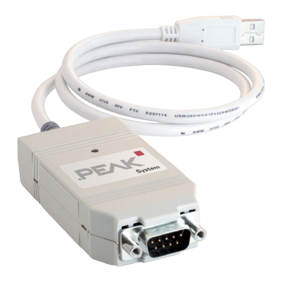
PCAN-USB USB to CAN Interface User Manual... - Page 2 Galvanic isolation for CAN IPEH-002022 interface The cover picture shows the product PCAN-USB. The case of the opto-decoupled version has a similar profile, but is longer. Product names mentioned in this manual may be the trademarks or registered trademarks of their respective companies. They are not explicitly marked by “™” and “®”.
-
Page 3: Table Of Contents
PCAN-USB – User Manual Contents Introduction Properties at a Glance System Requirements Scope of Supply Installation Installing the Software and the PCAN-USB Adapter Connecting the CAN Bus Supplying External Devices via the CAN Connector Operation Status LED Removing the Adapter Safely... -
Page 4: Introduction
PCAN-USB – User Manual Introduction The PCAN-USB adapter provides one CAN channel at computers with USB ports. Software interfaces exist for different operating systems, so programs can easily access a connected CAN bus. Tip: At the end of this manual (Appendix B) you can find a... -
Page 5: System Requirements
PCAN-USB – User Manual Note: This manual describes the use of PCAN-USB adapter with Windows. You can find device drivers for Linux and the corres- ponding application information on the provided CD in the directory branch Develop and on our website under www.peak-system.com/linux. -
Page 6: Installation
PCAN-USB – User Manual Installation This chapter deals with the software setup for the PCAN-USB adap- ter under Windows, the connection of the adapter to the computer, and the connection of a CAN bus. Installing the Software and the PCAN-... -
Page 7: Connecting The Can Bus
PCAN-USB – User Manual Do the following to connect the PCAN-USB adapter and complete the initialization: Connect the PCAN-USB adpater to an USB port of the computer or of a connected USB hub. The computer can remain powered on. Windows notifies that new hardware has been detected. -
Page 8: Supplying External Devices Via The Can Connector
ISO 11898-3). Supplying External Devices via the CAN Connector On the PCAN-USB PCB (PCAN-USB case opened) a 5-Volt supply can optionally be routed to pin 1 and/or pin 9 of the D-Sub CAN connector (PCAN-USB opto-decoupled: pin 1 only). Thus devices with low power consumption (e.g. - Page 9 PCAN-USB – User Manual Proceed as follows to activate the 5-Volt supply: In order to access the PCB, open the case of the PCAN-USB adapter by cautiously pushing in the latches on both sides, e.g. with a flat tip screwdriver.
- Page 10 PCAN-USB – User Manual Figure 3: Bottom side of the PCAN-USB opto-decoupled PCB, solder field R11 5-Volt supply → None Pin 1 PCAN-USB opto-decoupled, solder field R11 For reassembly place the PCB overhead onto the top part of the case. Ensure that the cable is lying with the strain relief in the cut- out of the case, and that the LED is placed in the corresponding hole.
-
Page 11: Operation
PCAN-USB – User Manual Operation Status LED The PCAN-USB adapter has a red status LED which may be in one of the following conditions: Off: A connection to a driver of the operating system is not established. On: The adapter is initialized. There's a connection to a driver of the operating system. - Page 12 PCAN-USB – User Manual After clicking on the icon select the command Remove PCAN-USB Device. After the red LED on the PCAN-USB adapter has gone out you can remove it from the USB port of the computer.
-
Page 13: Software
PCAN-USB – User Manual Software This chapter deals with the provided software and the software interface to the PCAN-USB adapter. CAN Monitor PCAN-View for Windows PCAN-View for Windows is a simple CAN monitor for viewing and transmitting CAN messages. Figure 5: The main window of PCAN-View for Windows... - Page 14 PCAN-USB – User Manual The dialog box for selecting the CAN hardware and for setting the CAN parameters appears. Figure 6: Selection of the CAN specific hardware and parameters From the list Baud rate select the transfer rate that is used by all nodes on the CAN bus.
-
Page 15: Linking Own Programs With Pcan-Light
On the provided CD you can find files for software development in the directory branch Develop. They exclusively serve the linking of own programs to hardware by PEAK-System with the help of the installed device driver under Windows. Further more the CD-ROM contains header files and examples for creating own applications in conjunction with the PCAN-Light drivers. -
Page 16: Technical Specifications
200 mA Connectors Computer USB plug type A D-Sub (m), 9 pins Pin assignment according to specification CiA 102 PCAN-USB opto-decoupled: galvanic isolation up to 500 V Type USB 1.1, compatible to USB 2.0 Specification ISO 11898-2 High-speed CAN (up to 1 Mbit/s) 2.0A (standard format) and 2.0B (extended format) - Page 17 PCAN-USB: 75 x 43 x 22 mm (2 15/16 x 1 11/16 x 7/8 inches) (L x W x H) PCAN-USB opto-dec.: 87 x 43 x 22 mm (3 7/16 x 1 11/16 x 7/8 inches) (L x W x H)
-
Page 18: Appendix A Certificates
PCAN-USB – User Manual Appendix A Certificates CE PCAN-USB... -
Page 19: Ce Pcan-Usb Opto-Decoupled
PCAN-USB – User Manual CE PCAN-USB opto-decoupled... -
Page 20: Appendix B Quick Reference
Appendix B Quick Reference Software/Hardware Installation under Windows Before connecting the PCAN-USB adapter to the computer set up the corresponding software package from the supplied CD (with administrator privileges). Afterwards connect the PCAN-USB adpater to an USB port at your computer. The adapter is recognized by Windows and the driver is initialized.
Need help?
Do you have a question about the PCAN-USB and is the answer not in the manual?
Questions and answers