
Related Manuals for Elmo i-Pochette


Summary of Contents for Elmo i-Pochette
-
Page 1: Document Camera
DOCUMENT CAMERA Instruction Manual Please read this instruction manual carefully before using this product and keep it for future reference. English - 0... -
Page 2: Table Of Contents
3.1 System diagram................... 15 3.2 Setting up..................... 16 3.3 Connecting devices ................17 3.4 Start using the i-Pochette ..............19 4 Operation Procedure.................. 20 4.1 Presentation using printed materials, etc..........20 4.2 Presentation using the supplied software with the USB-connected PC21 4.3 Presentation using a Microscope. -
Page 3: Important Safeguards
IMPORTANT SAFEGUARDS Read Instructions All the safety and operating instructions should be read before the appliance is operated. Retain Instructions The safety and operating instructions should be retained for future reference. Heed Warnings All warnings on the product and in the operating instructions should be adhered to. - Page 4 polarized 2-wire AC line plug (a plug having one blade wider than the other) or a 3-wire grounding type plug, a plug having a third (grounding) pin. The 2-wire polarized plug will fit into the power outlet only one way. This is a safety feature.
- Page 5 instructions. Adjust only those controls that are covered by the operating instructions as an improper adjustment of other contro ls may result in damage and will often require extensive work by a qualified technician to restore the product to its normal operation. If the product has been dropped or damaged in any way.
- Page 6 WARNING: FOR UNITED STATES TO REDUCE THE RISK USERS: OF FIRE OR ELECTRIC INFORMATION This equipment has been tested SHOCK, DO NOT and found to comply with the EXPOSE THIS limits for a Class A digital PRODUCT TO RAIN OR device, pursuant to Part 15 of MOISTURE.
-
Page 7: Before You Use
BEFORE YOU USE Use the product under the rated ele trical conditi ons. The power cord applicable to the local powe r specific ations is attached.Be sure to use the power cord applicab le to your local p ower specifications. Do not leave thi s product under direc t sunlight or by heaters, or it m... - Page 8 If this product is used for longer t han the warranty period, its performance and quality may deteriorate due t o the lifetime of its parts. In this case, we will replace the parts for a charge. Consult the seller from whom you have purchased this product or our branch/office near your location.
-
Page 9: Package Content
1 Package Content i-Pochette Quick Start Guide Power Cord AC Adapter Microscope Adapter Appearance may vary with country/region. C-Video Cable RGB Cable USB Cable Carrying Bag English - 8... -
Page 10: Part Names And Functions
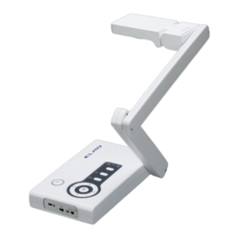
2 Part names and Fun ctions 2.1 N ame of e ach part Appearance Camera head Camera column Power button Func tions buttons Rear panel English - 9... -
Page 11: Functions
2.2 Functions 2.2.1 Functions buttons Name Function To turn ON/OFF the power. Power ON:Blue light turns on. Power OFF standby:Red light turns on. Increase the image size. Decrease the image size. 1.Automatically adjust focal length on an object. 2.Enter:Playback full image in Playback mode. 3.Enter:Go back thumbnail in Full image mode. - Page 12 Switch between different sources of signals : 1. Comp uter 2. Cam 3. Internal memory Clear all captured images in memory mode. Press the first then press together. Enter to the Service Menu Press the first then press together for 5 seconds. English - 11...
-
Page 13: Rear Panel
2.2.2 Rear Panel Name Function DC IN 12 V Plug-in for the AC adapter. VIDEO To output image from the RCA pin-jack terminal to the NTSC/PAL-system monitor (e.g., TV monitor). RGB OUT To output analog video signal to the projector, the PC. monitor or other RGB input device. -
Page 14: Side Panel
2.2.3 Side Panel Name Function VIDEO / RGB To switch the RGB (default) or Video mode. Video mode: RGB mode: RGB output is not supported once VIDEO output is enabled. The unit must be turned OFF to change the mode. XGA / To switch the resolution : XGA (default) / SXGA / WXGA SXGA /... - Page 15 2.2.4 Bottom panel Name Function 0Hz, 60Hz o switch the N TSC(default) or PAL mode. TSC, PAL NTSC PAL: The unit must be turned OFF to change the mode. o switch the 60Hz (default) or 50 Hz output mode. 60Hz: 50Hz: The unit must be turned OFF to change the ode.
-
Page 16: Installation And Connections
Installation an d Connections 3.1 System diagram English - 15... -
Page 17: Setting Up
3.2 Setting up Be sure to hold the lower part of the main unit in both hands when carrying the unit. Never hold the column or the camera head. Pay attention to prevent the camera head from knocking against the desk or the like. -
Page 18: Connecting Devices
Connect the RGB OUT on the i-Po chette to the RGB IN on the projector or monitor using the supplied RGB cable. Connecting to a TV 1. Using the supplied video cable to connect VI DEO of i-Pochette to a C-Video of TV. English - 17... - Page 19 : Country/region not listed above: DIP Switch setting will not be available until restarting the i-Pochette. Connecting to a com puter Use supplied RGB cable to connect RGB IN connector on i-Pochette the RGB OUT connector on the computer. English - 18...
-
Page 20: Start Using The I-Pochette
Turn the power button of th e main unit ON. Once i-Pochette is turned on, the LED on the control panel will flash a few times and stay lit. Please contact your distributor if the LED is not English - 19... -
Page 21: Operation Procedure
peration Pro cedure 4.1 Pre sentation using printed m aterials, etc. 4.1.1 Setting th e main unit: Set the main unit as sho wn in the above figure, connect the main unit to the projecto r or the PC monitor, and then turn the power button of the main unit ON. - Page 22 4.2 Presentation using the supplied software with the USB-connected PC .1 Install "Image Mate" Software “Image Mate ” can be fou nd on the supplied CD-ROM. The "Image Mate" and TWAIN driver "Image Mate TWAIN" software for controlling this device can be found on the CD-ROM and allows you to perform the following functions.
-
Page 23: Presentation Using A Microscope
4.3 Presentation using a Microscope. 4.3.1 Setting a microscope Place an object such as a prep ared slid e on a microscope. Adjust focus by checking with eyes at the microscope side. .2 Setting the main unit Connect the main unit to a projector or a PC monitor. Then turn the powe switch of the main unit ON. -
Page 24: How To Switch Image Sources
4.4 How to switch image sources Live image is the default of image source. Press source button on the control panel to change: 1. Camera (default) 2. Computer 3. Internal memory 4.5 Ho w to zoom in /out of images 1. -
Page 25: How To View Captured Images
4.9 How to view captured images 1. Press source button on the control panel to switch to camera to display captured ima ges. 2. Press to select the thumbnail you want you view. 3. Press for the full-screen display of the image. 4. -
Page 26: Troubleshooting
5 Troubleshooting This ch apter describes problems you may encounter while using i-Pochette. If you have que stions, please refer to related chapters and follow all the suggested solutions. If the problem st ill occ urre d, pl se contact our distributors or service center. -
Page 27: Specifications
6 Specifications General Item Specification Lens : F3.0,f=3.39mm sor : 1/4" UXGA CMOS Image Sensor IO connector : Rear of Platform SB : Type B GB IN : HD-15P, Female B OUT : HD-15P, Female IDEO : RCA Jack C IN 12V Side of Platform ck :Security Slot... -
Page 28: Supplied Accessories
Input Selection Camera/PC/ Memory Capture Freeze Max Shooting Area Min : <= 53x40mm in XGA Min Shooting Area Max : >=340mm x 255mm in XG Supplied Accessories Name Quantity AC Cord AC Adapter C-Video Cable Analog RGB Cable USB Cable Microscope Adapter Carrying Bag(Body) CD-ROM... - Page 29 ち切り後8 年間保有しています。この 部品保 有期間を修理可能の期間とさせていただきま す。 OVERSEAS SUBSIDIARY COMPANIES ●カメラシステムを使用して撮影する人物・そ の他の映像で、個人を特定できるものは個人 U.S.A. 情報となります。その映像の開示・公開等の 取扱いは、システムを運用する方の責務とな ELMO USA C りますので、ご注意ください。 WARNING Headquarters 1478 Old Country Road authorized recording of cop yrighted side Plainview, NY 11803-5034, U.S.A film s, materials, photograp hs, etc. may...
Need help?
Do you have a question about the i-Pochette and is the answer not in the manual?
Questions and answers