
Related Manuals for Elmo TT-02U


Summary of Contents for Elmo TT-02U
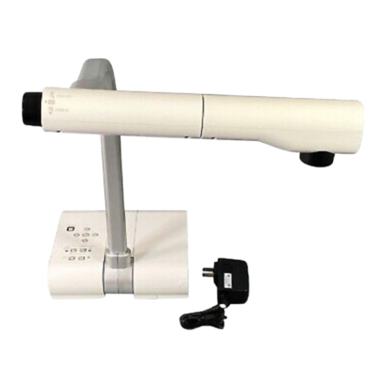
- Page 1 English P1~P33 Teacher’s Tool INSTRUCTION MANUAL Please read this instruction manual carefully before using this product and keep it for future reference.
-
Page 2: Important Safeguards
IMPORTANT SAFEGUARDS Read Instructions All the safety and should use a mounting and operating instructions should accessory recommended by the be read before the appliance is manufacturer. operated. Ventilation Slots and openings Retain Instructions The safety in the cabinet are provided for and operating instructions should ventilation and to ensure reliable be retained for future reference. - Page 3 English P1~P33 Grounding or Polarization This power-line surges. product may be equipped with Overloading Do not overload either a polarized 2-wire AC line wall outlets, extension cords, or plug (a plug having one blade integral convenience receptacles wider than the other) or a 3-wire as this can result in a risk of fire grounding type plug, a plug or electric shock.
- Page 4 Damage Requiring Service Heat The product should be Unplug this product from the situated away from heat sources wall outlet and refer servicing to such as radiators, heat registers, qualified service personnel under stoves, or other products the following conditions: (including amplifiers) that produce heat.
- Page 5 English P1~P33 WARNING: FOR UNITED STATES USERS: TO REDUCE THE RISK INFORMATION OF FIRE OR ELECTRIC This equipment has been tested and found to comply with the limits for SHOCK, DO NOT EXPOSE a Class B digital device, pursuant THIS PRODUCT TO RAIN to Part 15 of the FCC Rules.
-
Page 6: Before You Use
BEFORE YOU USE AC adapter applicable to the local power specification is attached. Use the AC adapter attached to the products in Nor th America market(AC120V 50/60Hz). Do not leave this product under direct sunlight or by heaters, or it may be discolored, deformed or damaged. - Page 7 English P1~P33 Use (including set-up and storage) or transfer with your closest attention to prevent the camera head from shocking. When a magnetic sheet is brought close to a cathode ray tube (Braun tube), a speaker, a CD-player, a DVD, or cellular phone, etc, the normal operation may be interrupted or failure may occur.
-
Page 8: Table Of Contents
CONTENTS IMPORTANT SAFEGUARDS ..............1 BEFORE YOU USE ................... 6 CONTENTS ....................8 1.PART NAMES AND FUNCTIONS ............9 Name of Each Part ................... 9 Appearance ....................9 Functions ......................10 Operating buttons ..................10 Rear Panel ....................11 OSD (On Screen Display) ................12 2.SETTING UP .................. -
Page 9: Part Names And Functions
English P1~P33 PART NAMES AND FUNCTIONS Name of Each Part Appearance Front Rear (10) Name Name Camera head Stage positioning P.19 Zoom dial Rear panel P.24 P.11 AF Button Stage P.25 P.19 Camera column Magnetic sheet P.19 Operating button (10) Anti-glare sheet P.10 P.19... -
Page 10: Functions
Functions Operating buttons (2)(4) (10) Name Function Name Function To turn ON/OFF (6) Image To turn on when POWER the power. select the camera (Power switch ON/ Power ON: Green (Camera image is selected OFF standby) light turns on image as the output Power OFF standby: selection... -
Page 11: Rear Panel
English P1~P33 Rear Panel Name Function (1) DC IN 12V Plug-in for the AC adapter (Power Socket) (2) RGB OUT To output analog video signal to the projector, the PC (Analog RGB monitor or other RGB input device. Output Terminal) P.15 (3) RGB IN To output the image input to this terminal, when [PC] is... -
Page 12: Osd (On Screen Display)
OSD (On Screen Display) The menu items displayed/selected on the monitor or the projection screen are referred to as “OSD (On-Screen Display).” When the [MENU] button is pressed, the OSD menu appears on the monitor screen. (By pressing the [MENU] button again, the OSD menu disappears.) Move the cursor to the item to be set with the direction buttons [ ] and press operating button [... - Page 13 English P1~P33 The top hierarchy The 2nd hierarchy Function White Balance Auto To set the white balance to Auto. P.29 One-Push To set the white balance to One-Push. P.29 Manual To manually adjust the red/blue elements. P.29 R-Gain (Displayed in level bar) To adjust the red element when the white balance is set to Manual.
-
Page 14: Setting Up
SETTING UP Setting Up Note • Be sure to hold the lower part of the main unit in both hands when carrying the unit. Never hold the column or the camera head • Pay attention to prevent the camera head from knocking against the desk or the like. -
Page 15: Connecting Of Ac Adapter And Video Cable
English P1~P33 Connecting of AC adapter and Video cable (5) DC IN 12V terminal • To power plug (1) RGB OUT terminal (4) USB terminal • To projector (2) RGB IN terminal • To PC • To PC monitor (3) VIDEO OUT terminal •... - Page 16 (3) Connecting to the unit with composite video input terminal equipped Connect the video cable with RCA pin plug to the [VIDEO OUT] terminal on the rear panel. (4) Connecting to the PC with a USB cable Connect a USB cable to the [USB] terminal on the rear panel. Note •...
-
Page 17: Storing
English P1~P33 STORING Storing Turn the power switch of the main unit (Continuously press the power switch for approx. 2 sec. The green light turns to red and the power switch of the main unit is OFF.) Note • Before storing, be sure to check if the lens returned to the proper position after the power switch of the main unit is OFF. -
Page 18: Operation Procedure
OPERATION PROCEDURE Presentation using printed materials, etc. Setting the main unit Set the main unit as shown in the above figure, connect the main unit to the projector or the PC monitor, and then turn the power switch of the main unit ON. Adjusting the size Place an object, adjust the position of the object with the zoom dial so that the objective part fits the screen size. -
Page 19: Presentation Using Printed Materials, Etc. (Using The Stage)
English P1~P33 Presentation using printed materials, etc. (Using the stage) Using the supplied stage, magnetic sheet or anti-glare sheet, effective presentation is possible. Setting the main unit Attach the stage to the specified position as shown in the above figure and connect to the projector or the PC monitor. -
Page 20: Presentation Using The Supplied Software With The Usb-Connected Pc
“Utility Software” is in the supplied CD-ROM. “Utility Software” contains the PC link software “Image Mate for Presentation” and the TWAIN driver “ELMO TWAIN DS (VHM)” for the following operations: • Transfer of moving/still images to the PC • Operation of this product from the PC The PC equipped with Microsoft Windows 2000(SP4 or newer)/XP(SP2 or newer) is recommended. -
Page 21: Presentation Using A Microscope
English P1~P33 Presentation using a Microscope Adjust Adjust Setting a microscope Place an object such as a prepared slide on a microscope. Adjust focus by checking with eyes at the microscope side. Setting the main unit Connect the main unit to a projector or a PC monitor. Then turn the power switch of the main unit ON. -
Page 22: Shooting A 3-D Object
Shooting a 3-D object Adjust Adjust Adjust By adjusting angle of the camera column and the camera head, a 3-D object can be shot from the side. Setting the main unit Connect the main unit to a projector or a PC monitor. Then turn the power switch of the main unit ON. -
Page 23: Shooting Wall Surface Or Distant View
English P1~P33 Shooting wall surface or distant view Forward shooting Backward shooting When the camera head is set horizontally, wall, distant view, etc, can be shot. Note • To shoot forward of the main unit, set to [Image Rotation] → [On] in the OSD to rotate the image by 180°. -
Page 24: Various Functions And Operations
VARIOUS FUNCTIONS AND OPERATIONS Zoom WIDE TELE The display range of the document can be adjusted by rotating the zoom dial. (Zoom-OUT ) : Object can be shown in small size. (Zoom-IN ) : Object can be shown in large size. Note •... -
Page 25: Focus
English P1~P33 Focus Push ■ Auto focus Press the [AF] button to automatically focus. The unit provides one-shot auto-focus system. Once the camera is focused, the auto focus operation is released, and then focus position is maintained. Note The objects listed below may not be brought into focus in the auto focus. In such cases, use the manual focus. -
Page 26: Manual Focus
■ Manual focus The position to focus can be changed with [ ] [ ] buttons MENU Focus on the main unit after selecting [Focus] in the OSD menu. Brightness Mode Use the manual focus to focus on any position of a 3-D Pause Image Rotation object. -
Page 27: Adjusting The Brightness
English P1~P33 Adjusting the brightness Press the [BRIGHTNESS • ] and [BRIGHTNESS • ] buttons on the main unit to adjust image brightness. Following two adjustment mode can be selected from the OSD menu. ■ Automatic brightness adjustment MENU SELECT ([Brightness] →... -
Page 28: Image Selection
Image selection The camera image and the image input in the RGB input terminal [RGB IN] can be switched by pressing the [CAMERA] button and the [PC] button respectively. By using these functions, output images can be switched without disconnecting cables. Note •... -
Page 29: White Balance
English P1~P33 White Balance ■ How to use [Auto] Adjust the white balance automatically according to the color SELECT MENU Microscope status of the document. White Balance Auto R-Gain One-Push Factory setting : Auto B-Gain Manual Posi/Nega ■ How to use [One-Push] To be used when the color balance of the image is lost. -
Page 30: Save/Call Setting
Save/call setting The operation status of the unit can be saved/called in the memory. The unit saves 4 conditions (1-3, ON setting) and the storable condition are as follows. • Current zoom angle of view • Status of white balance (The range of the optical zoom) •... -
Page 31: Trouble Shooting
English P1~P33 TROUBLE SHOOTING Symptoms and Confirmation Check the following items. If any abnormality is found, consult the seller from whom you have purchased this product or our branch/office near your location. Symptom Possible cause/counter measure No image is • The cable is not correctly connected. displayed. -
Page 32: Specifications
SPECIFICATIONS General Item Specifi cations Power source 12VDC (AC adapter AC100 - 240V) Power consumption 9W (AC adapter included) W343xD368xH411mm (W13.5xD14.5xH16.2 in) (When setup) Outside dimensions W195xD368xH444mm (W7.7xD14.5xH17.5 in) (When folded) Weight Approx. 2.9kg (6.4 lbs) (Main body only) Input selection Main/External Output terminal RGB output Mini Dsub 15P connector, female x 1... -
Page 33: Supplied Accessories
Utility Software Installation Manual Utility Software CD-ROM USB cable (1.8m) Trademark is the trademark of ELMO Co., Ltd. VESA and SVGA are the registered trademarks of Video Electronics Standards Association. VGA and XGA are the trademark/registered trademark of International Business Machines Corporation. - Page 35 Français P35~P67 Outil à enseigner MODE D’EMPLOI Lire attentivement ce mode d’emploi avant de mettre le Présentateur Visuel en marche. Le conserver à titre de référence permanente.
-
Page 36: Conseils Importants De Sécurité
CONSEILS IMPORTANTS DE SÉCURITÉ Lire les instructions - Toutes Support - Ne pas placer les instructions concernant cet appareil sur un support, la sécurité et l’utilisation de table, étagère, trépied ou l’appareil doivent être lues chariot instable. Il pourrait avant de le mettre en marche. tomber et causer une blessure grave à... - Page 37 Français P35~P67 Mise à la terre et polarisation Foudre - Pour assurer la - Ce produit peut être équipé protection de l’appareil contre soit d’un cordon d’alimentation la foudre, s’il doit rester CA à 2 conducteurs (une des sans surveillance pendant broches étant plus large que une longue période, il faut le l’autre), soit d’un cordon à...
- Page 38 Réparation – Ne pas essayer de pièces non autorisées peut causer un incendie, un risque de réparer l’appareil soi-même. Ouvrir et enlever les panneaux électrique ou un autre incident. de protection peut exposer à Contrôle de sécurité – Après un haut voltage et à d’autres réparation ou intervention, dangers.
- Page 39 Français P35~P67 Le symbole de l’éclair à tête FOR UNITED STATES USERS: deflèche dans un triangle équilatéral,avertit l’utilisateur de INFORMATION la présencede courant électrique This equipment has been tested and non-isolé deforte amplitude, à found to comply with the limits for l’intérieur del’appareil;...
-
Page 40: Avant L'emploi
AVANT L’EMPLOI L’adaptateur CA adapté au secteur local est fourni avec l’appareil. S’assurer d’utiliser l’adaptateur CA fourni avec les produits destinés au marché américain du nord (CA de 100V et 50/60 Hz). Ne pas exposer ce produit aux rayons directs du soleil ou au rayonnement d’un radiateur. - Page 41 Français P35~P67 Transporter l’appareil en tenant sa partie inférieure avec les deux mains. Ne jamais tenir l’appareil par la colonne ou la tête de caméra. Lors de son utilisation (y compris mise en marche et rangement) ou de son transport, faire très attention de ne pas heurter la tête de caméra. Lorsqu’une feuille magnétique est placée à...
-
Page 42: Sommaire
SOMMAIRE CONSEILS IMPORTANTS DE SÉCURITÉ ..........36 AVANT L’EMPLOI .................... 40 SOMMAIRE ....................42 1.NOMENCLATURE ET FONCTIONS ............. 43 Nomenclature ....................43 Présentation ....................43 Fonctions ......................44 Boutons de commande ................44 Tableau arrière .................... 45 OSD (Affi chage sur écran) ................46 2.MISE EN MARCHE ................ -
Page 43: Nomenclature Et Fonctions
NOMENCLATURE ET FONCTIONS Français P35~P67 Nomenclature Présentation Avant Arrière (10) Nº Nº Tête de caméra Positionnement de la platine P.53 Cadran de zoom Tableau arrière P.58 P.45 Bouton AF Platine P.59 P.53 Colonne de caméra Feuille magnétique P.53 Bouton de commande Feuille antirefl... -
Page 44: Fonctions
Fonctions Boutons de commande (2)(4) (10) Fonction Fonction Pour la mise (6) Sélection S’allume quand POWER sous/hors tension. d’image l’image caméra (interrupteur Mise sous tension : Le est sélectionnée (Lampe de principal ON/OFF en voyant vert s’allume comme image de signalisation attente) Mise hors tension/en... -
Page 45: Tableau Arrière
Français P35~P67 Tableau arrière Fonction (1) ENTREE 12V CC Fiche pour l’adaptateur CA (fi che d’alimentation) (2) RGB OUT Sortie de signaux vidéo analogiques sur le projecteur, (borne de sortie sur le moniteur du PC ou sur tout autre dispositif de RGB analogique) d’entrée RGB. -
Page 46: Osd (Affi Chage Sur Écran)
OSD (Affichage sur écran) L’ensemble des menus affichés ou sélectionnés sur le moniteur ou l’écran projeté est désigné ci-après comme “OSD“ (On-Screen Display). Déplacer le curseur jusqu’à l’article en question au moyen des boutons de déplacement ] et appuyer sur le bouton de commande [ ] afin de valider la sélection. - Page 47 Français P35~P67 1ère hiérarchie 2ème hiérarchie Fonction White Balance Auto Réglage de la balance des blancs sur Auto. P.63 One-Push Réglage de la balance des blancs sur One-Push (un seul appui) P.63 Manual Réglage manuel des composantes rouge et bleue. P.63 R-Gain (Affi...
-
Page 48: Mise En Marche
MISE EN MARCHE Opération de mise en marche Note • Lors du transport de l’appareil, tenir la partie inférieure du boîtier avec les deux mains. Ne jamais tenir l’appareil par la colonne ou la tête de caméra. • Faire attention à ce que la tête de caméra ne cogne pas contre le bureau ou le socle. -
Page 49: Branchement De L'adaptateur Ca Et Du Câble Vidéo
Français P35~P67 Branchement de l’adaptateur CA et du câble vidéo (5) Connecteur DC IN 12V • Vers une prise de courant (1) Connecteur RGB OUT • Vers le projecteur (4) Connecteur USB • Vers le moniteur (2) Connecteur RGB IN •... - Page 50 (3) Branchement à une unité dotée d’un connecteur d’entrée vidéo composite Brancher le câble vidéo doté d’une prise à broches RCA au connecteur [VIDEO OUT] du panneau arrière. (4) Branchement à un PC avec un câble USB Brancher un câble USB au connecteur [USB] du panneau arrière. Note •...
-
Page 51: Rangement
RANGEMENT Français P35~P67 Rangement Mettre l’interr upteur pr incipal de l’appareil hors tension (OFF). (Appuyer sur l’interrupteur principal pendant 2 secondes environ. L’interrupteur principal de l’ appareil est mis hors tension lorsque le voyant vert change au rouge.) Note • Avant le rangement, s’assurer que l’objectif est bien rangé... -
Page 52: Procéedures De Fonctionnement
PROCÉEDURES DE FONCTIONNEMENT Présentation au moyen de visuels imprimés ■ Installation de l’appareil principal Mettre l’appareil dans la configuration montrée ci-dessus, le relier au projecteur ou à un moniteur de PC et mettre l’appareil sous tension. ■ Réglage de la taille Placer un objet sur la platine et régler sa position au moyen du cadran de zoom de manière à... -
Page 53: Présentation Au Moyen De Visuels Imprimés, Etc. (À L'aide De La Platine)
Français P35~P67 Présentation au moyen de visuels imprimés, etc. (à l’aide de la platine) L’utilisation de la platine, de la feuille magnétique ou de la feuille antireflets fournie rend la présentation encore plus effective. ■ Installation de l’appareil principal Positionner la platine comme indiqué sur la figure ci-dessus et brancher l’appareil au projecteur ou au moniteur de PC. -
Page 54: Présentation Au Moyen D'un Pc Connecté En Usb Avec Le Logiciel Fourni
Le logiciel “Utility Software” est dans le CDROM fourni. Le CD-ROM “Utility Software” fourni contient le logiciel de liaison PC «Image Mate for Presentation» et le gestionnaire TWAIN «ELMO TWAIN DS (VHM)» pour les opérations suivantes : • Transfert des images animées/fixes à un PC •... -
Page 55: Prise De Vue Au Moyen D'un Microscope
Français P35~P67 Prise de vue au moyen d’un microscope Ajustement Ajustement ■ Mise en place d’un microscope Placer un objet tel qu’une diapositive sur un microscope. Effectuer la mise au point visuellement du côté microscope. ■ Installation de l’appareil principal Brancher l’appareil principal à... -
Page 56: Prise De Vue D'un Objet En 3D
Prise de vue d’un objet en 3D Ajustement Ajustement Ajustement Ajuster l’angle de la colonne de caméra et de la tête de caméra pour présenter l’objet en 3D latéralement. ■ Installation de l’appareil principal Brancher l’appareil principal à un projecteur ou un moniteur de PC. Ensuite, mettre l’interrupteur principal de l’appareil sous tension (ON). -
Page 57: Prise De Vue D'un Mur Ou D'un Paysage Lointain
Français P35~P67 Prise de vue d’un mur ou d’un paysage lointain Prise de vue avant Prise de vue arrière Il est possible de visionner un mur ou un paysage lointain si la tête de caméra est positionnée horizontalement. Note • Pour effectuer une prise de vue avant de l’appareil principal, faire tourner l’image de 180°... -
Page 58: Description Des Fonctions
DESCRIPTION DES FONCTIONS Zoom WIDE (grand angle) TELE (gros plan) Il est possible de régler la zone d’affichage d’un document en faisant tourner le cadran de zoom. (Faire un zoom vers plan général ) : L’objet apparaît plus petit. (Faire un zoom vers gros pla ) : L’objet apparaît plus grand Note •... -
Page 59: Mise Au Point
Français P35~P67 Mise au point Appui ■ Mise au point automatique Appuyer sur le bouton [AF] pour mettre au point automatiquement. Cet appareil est du type autofocalisation à coup unique. C’est à dire qu’une fois la mise au point de la caméra obtenue, la mise au point automatique est annulée et la position de mise au point est maintenue. -
Page 60: Mise Au Point Manuelle
■ Mise au point manuelle La position de mise au point peut être changée à l’aide des MENU Focus boutons [ ] [ ] sur l’appareil principal après sélection du Brightness Mode mode [Focus] dans le menu OSD. Pause Image Rotation Utiliser cette fonction pour obtenir la mise au point d’une partie quelconque d’un objet en 3D. -
Page 61: Réglage De La Luminosité
Français P35~P67 Réglage de la luminosité A p p u ye r s u r l e s b o u t o n s [ B R I G H T N E S S • ] e t [BRIGHTNESS •... -
Page 62: Sélection D'image
Sélection d’image L’image caméra et l’image d’entrée du connecteur d’entrée RGB [RGB IN] peuvent être commutées en appuyant sur le bouton [CAMERA] respectivement sur le bouton [PC]. Ces fonctions permettent de commuter des images de sortie sans débrancher des câbles. Note •... -
Page 63: Équilibre Des Blancs
Français P35~P67 Équilibre des blancs ■ Comment utiliser le mode [Auto] Réglage automatique de la coloration de blancs en fonction SELECT MENU Microscope de l’état d’un document. White Balance Auto R-Gain One-Push Réglage en usine : Auto B-Gain Manual Posi/Nega ■... -
Page 64: Sauvegarde/Appel Des Réglages
Sauvegarde/appel des réglages Il est possible de sauvegarder/appeler les réglages fonctionnels de l’appareil. Jusqu’à 4 réglages (1 – 3, ON) peuvent être sauvegardés. Les voici: • Angle actuel de champ de zoom • Etat de l’équilibre des blancs (la plage du zoom optique) •... -
Page 65: Dépannage
DÉPANNAGE Français P35~P67 Phénomènes et vérifications Contrôler les points suivants. Si un défaut a été constaté après ces contrôles, s’adresser au revendeur, à l’une de nos filiales ou à l’une de nos bureaux. Phénomène Cause possible/point à contrôler Aucune image n’est •... -
Page 66: Caracteristiques Techniques
CARACTERISTIQUES TECHNIQUES Caractéristiques générales Article Description Alimentation 12V CC (Adaptateur CA100 - 240V) Consommation 9W (Adaptateur CA incls.) L343xP368xH411mm (L13,5xP14,5xH16,2 po) (monté) Dimensions (extérieures) L195xP368xH444mm (L7,7xP14,5xH17,5 po) (plié) Poids Environ 2,9kg (6,4 lbs) (corps principal seulement) Sélection d’entrée Principal/externe Connecteur de sortie Sortie RGB Connecteur mini DSUB 15P, femelle x 1 Sortie vidéo composite Fiche RCA/75 Ω... -
Page 67: Accessoires Fournis
CD-ROM de logiciel d’utilité (Utility Software CD-ROM) Câble USB (1.8 m) Marques de commerce est une marque déposée de ELMO Co., Ltd. VESA et SVGA sont des marques déposées de Video Electronics Standards Association. VGA et XGA sont des marques déposées de International Business Machines Corporation.
Need help?
Do you have a question about the TT-02U and is the answer not in the manual?
Questions and answers