Advertisement
Table of Contents
- 1 Table of Contents
- 2 Safety Rules
- 3 Package Contents
- 4 Mounting Options
- 5 Installing the Fan
- 6 Hanging the Fan
- 7 Electrical Connections
- 8 Finishing the Installation
- 9 Attaching the Fan Blades
- 10 Light Kit Installation
- 11 Installing the Light Bulbs & Glass Shade
- 12 Operating Your Fan
- 13 Care of Your Fan
- 14 Troubleshooting
- 15 Specifications
- Download this manual
Advertisement
Table of Contents

Related Manuals for Minka-Aire SUPRA 44


Summary of Contents for Minka-Aire SUPRA 44
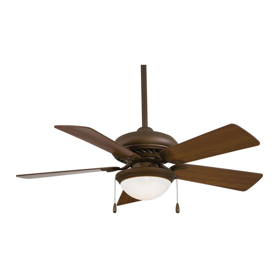
- Page 1 SUPRA 44 WITH LIGHT KIT U.S. Patent: D450,830 INSTRUCTION MANUAL WARRANTY CERTIFICATE...
- Page 2 This product is protected by United States Federal and/or State Law, including Patent, Trademark and/or Copyright laws. Manual design and all elements of manual design are protected by U.S. Federal and/or State Law, including Patent, Trademark and/or Copyright laws.
- Page 3 This is a limited warranty. Minka-Aire's only obligation under this limited warranty is to replace or repair, or refund the purchase price, in Minka-Aire's sole discretion without charge to the original owner, of the fan once Minka-Aire confirms that the fan has a defect covered by this limited warranty.
- Page 4 This limited warranty is in lieu of all other express warranties. This limited warranty excludes all incidental and consequential damages, and Minka-Aire shall not under any circumstances be liable for incidental or consequential damages. Some States do not allow the exclusion of or limitation of incidental or consequential damages, so the foregoing limitation or exclusion may not apply to you.
-
Page 5: Table Of Contents
CONTENTS SAFETY RULES................... ATTACHING THE FAN BLADES............PACKAGE CONTENTS..............LIGHT KIT INSTALLATION..............INSTALLING THE FAN..............INSTALLING THE LIGHT BULBS & GLASS SHADE ....HANGING THE FAN................ OPERATING YOUR FAN............... ELECTRICAL CONNECTIONS............CARE OF YOUR FAN................FINISHING THE INSTALLATION..........TROUBLESHOOTING................SPECIFICATIONS..................LISTED E75795 1151 W. -
Page 6: Safety Rules
SAFETY RULES 1. Before you begin installing the fan, shut power off at the circuit breaker of the fuse box. 2. Be cautious! Read all instructions and safety information before installing your new fan. Review accompanying assembly diagrams. 3. Make sure that all electrical connections comply with local codes, ordinances, or National Electrical Codes. Hire a qualified electrician or consult a do-it-yourself wiring handbook if you are unfamiliar with installing electrical wiring. - Page 7 ATTENTION: ATTENTION: The Energy Policy Act of 2005 requires this fan to be equipped with a 190 watt limiting device. If lamping exceeds 190 watts, the ceiling fan's light kit will shut off automatically. NOTE: The important safeguards and instructions appearing in this manual are not meant to cover all possible conditions and situations that may occur.
-
Page 8: Package Contents
PACKAGE CONTENTS Unpack your fan and check the contents. You should have the following items: A. Mounting hardware: 1. Fan blades (5) #10 x 1.5" Wood screws (2 PCs.) 2. Hanger bracket #8 x 3/4" Machine screws (2 PCs.) 3. Canopy Lock washers (2 PCs.) 4a. -
Page 9: Installing The Fan
To hang your fan where there is an existing fixture but no ceiling joist, you may need to install OUTLET BOX UPSIDE HANGER RECESSED BRACKET a hanger bar as shown in Fig. 4 (available at your Minka-Aire dealer). OUTLET BOX FIG. 3 FIG. 4... -
Page 10: Hanging The Fan
HANGING THE FAN WARNING: All of the parts, hardware and components such as the Step 3. Remove the Hanger Ball from the Downrod Assembly by loosening hanger bracket and hanger ball have been provided for your safety and the Set Screw and removing the Cross Pin. (Fig. 7) the proper installation of your new ceiling fan. - Page 11 DOWNROD OUTLET BOX COUPLING CANOPY DOWNROD *OMIT COUPLING CROSS PIN COVER WHEN SET SCREWS THE MINIMUM-LENGTH HITCH DOWNROD LOCK HANGER SUPPLY REGISTRATION BALL SET SCREW WIRES SLOT SET SCREWS DOWNROD HANGER BRACKET Fig. 10 Fig. 5 Fig. 6 Fig. 7 Fig.
-
Page 12: Electrical Connections
(Fig. 11) Step 3. Figure 12 & 13 Illustrate the wiring connections using optional wall unit. (Available at your Minka-Aire Retailer.) NOTE: If a light kit is not included with your fan, one can be purchased at your Minka-Aire Retailer Fig. - Page 13 FAN CONTROLLED BY PULL CHAIN, LIGHT KIT CONTROLLED BY WALL SWITCH. FAN CONTROLLED BY WALL CONTROL, LIGHT KIT CONTROLLED BY LIGHT SWITCH. HOUSE WIRE SUPPLY HOUSE WIRE SUPPLY WHITE (NEUTRAL) GREEN (GROUND) WHITE (NEUTRAL) GREEN (GROUND) BLACK (HOT) BLACK (HOT) CEILING CEILING LIGHT SWITCH...
-
Page 14: Finishing The Installation
FINISHING THE INSTALLATION OUTLET BOX Step 1. Slide the canopy up to the ceiling and over the two screws on hanger bracket. Rotate canopy clockwise until it stops, tighten screws. (Fig.14) HANGER BRACKET HANGER BALL CANOPY Fig. 14... -
Page 15: Attaching The Fan Blades
ATTACHING THE FAN BLADES Step 1. Attach the fan blades to the blade holders using the screws and fiber washers provided, tighten screws securely. (Fig. 15) SCREWS Step 2. Remove rubber stops from motor. FAN MOTOR FAN BLADE Rotate motor so that the screw holes are FIBER WASHERS revealed through the opening on switch cap... -
Page 16: Light Kit Installation
LIGHT KIT INSTALLATION NOTE: Before starting installation, disconnect the power by turning off the circuit breaker or removing the fuse at fuse box. Step 1. Remove and discard the center plug from the switch cup. (Fig. 17) LOCK WASHER Step 2. Feed the BLACK and WHITE wires from the light kit through the center hole of the switch cup. Thread the switch cup to the nipple on the light kit. -
Page 17: Installing The Light Bulbs & Glass Shade
INSTALLING THE LIGHT BULB & GLASS SHADE WARNING: Shut off the power supply before removing or replacing lamp. In handling of halogen bulb, SWITCH CUP care should be taken not to touch it with your bare hands. Oil residue will shorten the life of the PLATE halogen bulb. -
Page 18: Operating Your Fan
OPERATING YOUR FAN Restore power to ceiling fan and test for proper operation. Speed settings for warm or cool weather depend on factors such as the room size. Ceiling height, number of fans, etc. The Reverse switch is located on the switch cup. Slide the switch to the Left for warm weather operation. Slide the switch to the Right for cool weather operation. - Page 19 WINTER OPERATION SUMMER OPERATION Fig 19 Fig 20...
-
Page 20: Care Of Your Fan
CARE OF YOUR FAN Here are some suggestions to help maintain your fan. 4. There is no need to oil your fan. The motor has permanently lubricated bearings. 1. Because of the fan's natural movement some connections may become loose. Check the support connections, brackets and blade 5. -
Page 21: Troubleshooting
TROUBLESHOOTING SYMPTOM SYMPTOM Fan will not start Fan Sounds Noisy SOLUTION SOLUTION Check fuses or circuit breakers. Allow a 24-hour "break-in" period. Most noises as sociated with a new fan go away during this time. Check line wire connections to fan and switch wire connections in switch housing. - Page 22 SYMPTOM SYMPTOM Fan Wobble Lights shut off and will not come back on. SOLUTION SOLUTION Check that all blade and blade holder screws are secured. This unit is equipped with a wattage limiting device. Lamping in excess of 190 watts will disable your ceiling fan’s light kit. To reset your light kit you must Use the enclosed blade balancing kit if blade wobble is turn the power off and re lamp, keeping the wattage under 190 watts.
-
Page 23: Specifications
SPECIFICATIONS These are typical readings. Your actual fan may vary. They Fan Size Speed Volts Amps Watts RPM CFM N.W. G.W. C.F. do not include amps and wattage used by the light(s). 0.22 1370 9.92 11.22 1.786' 44" Medium 0.42 3458 High 0.63...
Need help?
Do you have a question about the SUPRA 44 and is the answer not in the manual?
Questions and answers