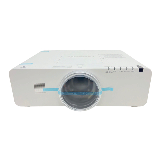
Panasonic PT-EX600U Service Manual

Panasonic PT-EX600U Service Manual

Hide thumbs Also See for PT-EX600U:
Table of Contents

Advertisement

Lens is optional for the projectors that "L" follows in model number.
*
ORDER NO. VED1205428CE

LCD Projector

PT-EX600U
Model No.
PT-EX600E
PT-EX600UL
PT-EX600EL
PT-EW630U
PT-EW630E
PT-EW630UL
PT-EW630EL
© Panasonic Corporation 2012.Unauthorized
copying and distribution is a violation of law.
D10

Advertisement

Table of Contents
loading

Summary of Contents for Panasonic PT-EX600U

  • Page 1: Lcd Projector

    ORDER NO. VED1205428CE LCD Projector PT-EX600U Model No. PT-EX600E PT-EX600UL PT-EX600EL PT-EW630U PT-EW630E PT-EW630UL PT-EW630EL Lens is optional for the projectors that “L” follows in model number. © Panasonic Corporation 2012.Unauthorized copying and distribution is a violation of law.
  • Page 2: Table Of Contents

    Contents Contents ............... 2 Motor control problems ..........90 Safety Instructions ............3 Bus control ..............91 Safety precautions ............4 LED drive & RC control ........... 92 Specifications .............. 5 Indicators and projector condition ......93 Circuit Protections ............7 If an indicator turns on ..........
  • Page 3: Safety Instructions

    IMPORTANT SAFETY NOTICE There are special parts used in Panasonic LCD Projectors which are important for safety. These parts are shaded on the sche- matic diagram. It is essential that these critical parts should be replaced with manufacturer’s specified parts to prevent shock, fire, or other hazards.
  • Page 4: Safety Precautions

    <PT-FW430U/PT-FW430E/PT-FW430EA/PT-FX400U/PT-FX400E/PT-FX400EA> Safety Instructions Safety precautions 1. Safety Precautions 1.1. General Guidelines - For continued safety, no modification of any circuit must be attempted. - Unplug the power cord from the power outlet before disassembling this projector. - Use correctly the supplied power cord and must ground it. - It is advisable to use an isolation transformer in the AC power line before the service.
  • Page 5: Specifications

    Specifications Model No. PT-EX600U / E / UL / EL PT-EW630U / E / UL / EL Power supply AC100 V - 240 V 50 Hz/60 Hz 100 V - 240 V 4.9 A-2.0 A 490 W When [Standby mode] of [Setting] is set to [ECO]: 0.4 W...
  • Page 6 *6: This is an average value. It may differ depending on individual product. It is only for PT-EX600UL, PT-EX600EL, PT_EW630UL and PT-EW630EL. *7: This is an average value. It may differ depending on individual product. It is only for PT-EX600U,PT-EX600E, PT-EW630U and PT-EW630E.
  • Page 7: Circuit Protections

    Circuit Protections This projector provides the following circuit protections to operate in safety. If the abnormality occurs inside the pro- jector, it will automatically turn off by operating one of the following protection circuits. Fuse(F601) Thermal fuse(SW902) A fuse is located inside of the projector. When the ON(G)/ There is the thermal fuse (SW902) inside of the projec- STANDBY(R) indicator is not lighting, the fuse may be tor to detect the internal temperature rising abnormally.
  • Page 8: Mechanical Sensor Switches

    Circuit Protections Mechanical sensor switches This projector provides 2 mechanical sensor switches, the one is for air filter unit switch (SW1891) and the other one is for lamp cover switch(SW901). The projector is shut down and the < ON(G)/STANDBY(R)> indicator lights in red and other indicators are blinking.
  • Page 9: Temperature Sensors, Wind Sensors

    Circuit Protections Temperature sensors, wind sensors The projector provides 3 temperature sensor ICs and 1 wind sensor on the intake duct. These devices are monitoring the surrounding temperature of the lamp, panel and intake duct, and the wind sensor is monitoring airflow passed through the air filter in the intake duct.
  • Page 10: Power Failure And Fan Lock Detection

    Circuit Protections Power failure and fan lock detection The projector provides the detection circuits of the power failure and the fan lock. When the detection circuit detects an error at the power supply line or at the fan operation circuit, the projector will turn into the standby mode to protect the other circuits defective.
  • Page 11: Maintenance

    Maintenance Before replacing the unit When you perform maintenance or replacement of the parts, make sure to turn off the power and disconnect the power plug from the wall outlet. Maintenance n Outer case Wipe off dirt and dust using a soft dry cloth. ò...
  • Page 12 Maintenance 5) Clean the air filter unit. Removing the dust from the air filter unit ò (i) Remove the dust from the air filter unit using a vacuum or other cleaner. • If the dust persists after cleaning with a vacuum, wash the air filter unit in water. Washing the air filter unit ò (i) Soak the air filter unit in water or warm water and rinse it lightly. • Do not use materials such as blushes or detergent.
  • Page 13: Replacing The Unit

    Maintenance Replacing the unit n Air filter unit The replacement filter is optional. To purchase the product, consult your deal- Replacement air filter unit : ET-RFE200 Reset the filter counter. • Turn on the power and perform [Filter counter reset] in the [Setting] menu. Attention • T urn off the power before you replace the air filter unit. • W hen attaching the air filter unit, make sure that the projector is stable, and work in an environment that is safe, even in the event of the air filter unit dropping. • D o not operate the projector with the air filter unit removed. Dust may accumulate on the optical elements degrading picture quality.
  • Page 14: Lamp Unit

    Maintenance n Lamp unit The lamp unit is a consumable component. You can check the total usage time using lamp runtime in the information menu. It is recommended to ask an authorized engineer to replace the lamp unit. Contact your dealer. Consult your dealer to purchase a replacement lamp unit.
  • Page 15: Replacing The Lamp Unit

    Maintenance Replacing the lamp unit CAUTION: • W hen the projector is mounted on a ceiling, do not work with your face close to the projector. Lamp cover • A ttach the lamp unit and the lamp cover securely. • W hen you experience difficulty in installing the lamp, remove it and try again. If you use force to install the lamp, the connector may be damaged.
  • Page 16: How To Check Lamp Runtime

    Maintenance How to check lamp runtime The LAMP indicator will light yellow when the lamp runtime (Corresponding value) reaches 3,000 hours. This is to indicate that lamp replacement is required. The lamp runtime is calculated by using the below expression. Lamp runtime (Corresponding value) = normal + eco x 0.75...
  • Page 17: Quick Maintenance

    Maintenance Quick maintenance This projector provides a cabinet prism cover on the cabinet top to enhance the service maintenance. This enables service personnel to align the optical adjustment or replace the optical parts without disassembly the cabinet top. Loosen 1 screw-A on the lamp cover and slide it to open (Fig.
  • Page 18: Removing And Attaching The Projection Lens

    Maintenance Removing and attaching the projection lens When replacing the lens or using an optional lens, install the lens by following the instructions below. Ask the sales dealer for detailed information of the optional lens specifications. Removing the lens „ Lens release button 1. Press and hold the <LENS> button or <LENS SHIFT> button for more than 5 seconds to make the lens return to the central position.
  • Page 19: Using The Lens Antitheft Screw

    Maintenance Using the lens antitheft screw This projector provides a lens antitheft screw to protect the projection lens stolen from a suspicious person. Mount the lens antitheft screw by following the instructions below. Mounting the lens antitheft screw Loosen a screw-A on the lamp cover and slide it to Lamp cover open (Fig.
  • Page 20: Cleaning

    Maintenance Cleaning After long periods of use, dust and other particles will accumulate on the LCD panel, prism, mirror, polarized glass, lens, etc., causing the picture to darken or color to blur. If this occurs, clean the inside of optical unit. Remove dust and other particles using air spray.
  • Page 21: Security Function Notice

    Security Function Notice This projector provides security functions such as "Key lock", "PIN code lock" and "Logo PIN code lock". When the projector has set these security function on, you are required to enter correct PIN code to use the projector. If you do not know the correct PIN code to the projector, the projector can no longer be operated or started.
  • Page 22: Standby Mode Notice

    Standby Mode Notice This projector provides 3 types of standby mode, Normal standby mode, Eco standby mode and Network standby mode. According to the standby mode "Normal", "Eco" or "Network", several functions are restricted as shown in the table below. To change the standby mode, use the projector's menu "Setting". Normal ....
  • Page 23: Mechanical Disassembly

    Mechanical Disassembly Mechanical disassembly should be made following procedures in numerical or- Screws expression der. (Type ) mm Diameter x Length Following steps show the basic procedures, therefore unnecessary step may T type M type be ignored. Caution: The parts and screws should be placed exactly the same position as the original otherwise it may cause loss of performance and product safety.
  • Page 24 Mechanical Disassembly 1. Lamp cover and prism cover removal 1. Loosen 1 screw-A and remove the lamp cover upward off. 2. Loosen 1 screw-B and remove the prism cover by sliding it in the arrow direction. Lamp cover Prism cover 2.
  • Page 25 Mechanical Disassembly 3. Fan (FN905) and main&AV board removal Prism cover 1. Remove 1 screw-A (M3x10) and 3 screws-B (T3x10) to take the fan (FN905) shield upward off. 2. Remove 2 screws-C(M3x6) and 1 screw-J(M3x10) to take the prism cover shield off.
  • Page 26 Mechanical Disassembly 4. Shutter and sensor C board removal 1. Remove 3 screws-A (M3x10) and 4 screw-B (T3x10) to take the main board shield bottom. 2. Loosen 1 hex screw-C and pull the shutter assy upward. Main board 3. Remove 1 screw-D (T3x8) to take the sensor C board off. shield bottom 4.
  • Page 27 Mechanical Disassembly 6. Projection lens removal 1. Press and hold the lens release button and turn the projection lens counter- clockwise until it stops and put it out slowly. Projection lens Lens release button 7. Optical unit removal 1. Remove 2 screws-A (T3x8)and 7 screws-B (T4x10) and remove the optical unit assy and lens shift assy.
  • Page 28 Mechanical Disassembly 7-1. Lens shift assy and Iris assy removel 1. Remove 4 screws-A (M3x8) to take the lens shift assy off. 2. Remove 4 screws-B (M3x14) to take the lens mount off. 3. Remove 3 screws-C (T3x8) to take the Iris assy. Lens mount Lens shift assy Iris assy...
  • Page 29 Mechanical Disassembly 8-1. Thermal fuse replacing 1. Remove the thermal fuse spacer from the thermal fuse mounting. 2. Remove the thermal fuse(SW902). 3. Mount the thermal fuses as shown in the figure below. Thermal fuse mounting Thermal fuse spacer Top view of the fuse mounting 8-2.
  • Page 30 Mechanical Disassembly 9. Control board and fans (FN902,FN903,FN904) removal 1. Remove 3 screws-A (T3x8) to take the lamp fan assy off. 2. Pull the holder on the control board up to release the hook and remove the Control board assy upward off. A A A T3x12 T3x12...
  • Page 31 Mechanical Disassembly 11. Fans (FN906, FN909, FN910) removal 1. Remove 3 screws-A (T3x14), 1 screw-B (T3x8) and unhook 2 hooks and remove the duct panel top. 2. Remove 3 screws-C (T3x8) to take the duct PBS off. 3. Remove 3 screws-D (T3x14) and 3 screws-E (T3x8) to take the duct fans assy off.
  • Page 32 Mechanical Disassembly 13. Cable reforming Reform the cables as shown in the figure below. Place the cables at the original position after replacing the parts. Lamp cover switch Wire band hook Guide hook Thermal fuse Wire band hook hook hook hook Ferrite core Note on fan's connection...
  • Page 33: Optical Parts Disassembly

    Optical Parts Disassembly Before taking this procedure, remove the cabinet top, main&AV board assy, projection lens, lamp assy and shutter assy refer to the “Mechanical disassembly”. Disassembly requires a 2.0mm hex wrench and a screwdriver. Note:To remove the LCD panel/prism assy and polarized glass-in, open the prism cover and then remove the shutter assy first.
  • Page 34 Optical Parts Disassembly 2. Polarized glass-in removal 1. Remove 2 screws-E (M2.5x6) each on the polar- ized glass assy and remove the stoppers, and pull the polarized glass assy upward (Fig.1). Polarized glass assy Fig. 1 Point marker Polarized glass-in (R) Film attached side comes to this side Point marker...
  • Page 35 Optical Parts Disassembly 3. PBS and integrator lens assy removal 1. Remove 2 screws-A (M3x14) and pull the PBS and Integrator lens assy upward. M2.5x6 M2.5x6 Stopper Stopper PBS and Integrator lens assy Stopper Integrator lens-out Integrator lens-in Top view of PBS and Integrator lens assy Cutting corner Rugged surface Integrator lens-out...
  • Page 36 Optical Parts Disassembly 4. Condenser lens assy removal 1. Remove 2 screws-A (M2.5x6) and pull the condenser lens assy upward. Condenser lens Flat surface assy side M2.5x6 M2x4 Condenser M2x4 lens Stopper 5. Optical parts in the optical unit removal 1.
  • Page 37 Optical Parts Disassembly 5-1. Mirror(B) assy and relay lens(IN) assy removal 1. Remove 2 screws-A (M2.5x6) and pull the mirror(B) assy upward off. 2. Remove 1 screw-B (M2.5x6) and 1 screw-C (M2x4), and pull the relay lens(In) assy upward off. Relay lens(In) assy Mirror(B) assy...
  • Page 38 Optical Parts Disassembly 5-2. Optical parts in the optical unit When mounting or assembling the optical parts in the optical unit, the parts must be mounted in the specified location and direction as shown in the figure below. Marking behind the mirror Marking behind the mirror...
  • Page 39: Servicing Notice

    Not defined 0 -> 10 Data Model no. PT-EX600 [ (refer t table right) Not defined PT-EW630 0 -> 10 PT-EX600 PT-EX600U [ (refer t table right) PT-EW630 PT-EW630U 0 -> 10 PT-EX600U PT-EX600E [ (refer t table right) PT-EW630U PT-EW630E 0 ->...
  • Page 40: Adjustment Data Setting

    Servicing Notice 2. Adjustment data setting This projector stores " Color shading correction data" and "Gamma correction data" in the memory IC (IC801) on the main board. Those adjustment data have been setup according to the optical characteristics of the mounted LCD pan- els preciously in the factory.
  • Page 41: Adjustments

    Adjustments Adjustments after parts replacement : Adjustment necessary : Check necessary ● ❍ Disassembly / Replaced parts Condenser lens (OUT)/ LCD/ Polarized Fans Wind Relay Power board Main board prism assy Glass Sensor lens (OUT)/ Integrator lens Optical axis adjustment ●...
  • Page 42: Optical Adjustments

    Optical Adjustments WARNING : USE UV RADIATION EYE AND SKIN PRO- TECTION DURING SERVICING CAUTION: To prevent suffer of UV radiation, those adjustment must be completed within 25 minutes. Before adjustment Each adjustment requires hex wrenches and slot screw- drivers. Move the projection lens position to center by pressing the LENS button for more than 5 seconds.
  • Page 43: Optical Axis Adjustment

    Optical Adjustments 1. Optical axis adjustment Select the internal test pattern signal “All white” from the projector’s menu “Menu -> Setting -> Test pattern”. 1-1. Condenser lens adjustment-1 Loosen 2 screws and 1 screws Move the condenser lens to display the color shading on the top/bottom and left/right of the screen.
  • Page 44 Optical Adjustments 1-2. Mirror (B) adjustment Loosen 1 screw and 1 screws Move the Mirror-B to disappear the color band (Yellow/Magenta) on the top/bottom and left/right of the screen. 1) Insert a slot driver into the slot and turn it to move the image vertically as shown in Fig.1-4.
  • Page 45 Optical Adjustments 1-3. Relay lens (R) adjustment Loosen 1 screw and 1 screw Move the Relay lens (R) so that the color shading appeared on the top/bot- tom and left/right of the screen becomes the same width. 1) Insert a slot driver into the slot and turn it to move the image horizon- tally as shown in Fig.1-5, 2) Insert a slot driver into the slot...
  • Page 46: Condenser Lens Adjustment

    Optical Adjustments 1-4. Condenser lens adjustment-2 Move the condenser lens to remove the color shading on the top/bottom or left/right of the screen. 1) Insert a slot driver into the slot and turn it to move the image horizon- tally as shown in Fig.1-7. 2) Insert a slot driver into the slot and turn it to move the image vertically as shown in Fig.1-8.
  • Page 47: Contrast Adjustment

    Optical Adjustments 2. Contrast adjustment Select the internal test pattern signal “All black” from the projector’s menu “Menu -> Setting -> Test pattern”. Turn the lever of polarized glass to obtain the darkest brightness and proper black color uniformity on the screen. * This adjustment should be taken in order of G-panel, R-panel and B-panel.
  • Page 48: Electrical Adjustments

    Electrical Adjustments Service adjustment menu operation To enter the service mode MENU button ENTER button To enter the “Service mode”, press and hold the on the projector for more than MENU button 3 seconds or press and hold the on the remote control for more than 20 seconds. The service menu appears on the screen as follows.
  • Page 49: Circuit Adjustments

    Electrical Adjustments Circuit adjustments CAUTION: The each circuit has been made by the fine adjustment at factory. Do not attempt to adjust the following adjustments except requiring the readjustments in servicing otherwise it may cause loss of performance and product safety. Before adjustment, please turn on the projector for more than 10 minutes to stabilize the operation.
  • Page 50 Electrical Adjustments 1. Fan voltage adjustment Adjustments item no. [3] and [5] are carried out Equipment Digital voltmeter at the spare parts shipment in the factory, there- fore they are not required when the main board is 1. Enter the service mode. replaced with new one.
  • Page 51 Electrical Adjustments 3. Auto calibration adjustment [PC] 5. Auto calibration adjustment [Video] (For PT-EW630) (For PT-EW630) Input mode Input 1 (RGB(PC analog)) Input mode Input 3 (Video) Input signal XGA computer signal Input signal 100% color bar composite video signal Signal pattern 16-step gray scale 1.
  • Page 52 Electrical Adjustments 6. Common center adjustment 9. Color shading correction adjustment Input mode Input 1 (RGB(PC analog)) (For PT-EW630) Input signal XGA computer signal Software PROJECTOR SERVICE TOOL v4.20 Signal patterns 50% R, G, B whole signals Signal pattern 5%, 10%, 15%, 20%, 30%, 50%, 75%, 85% whole gray 1.
  • Page 53: Test Points And Locations

    Electrical Adjustments Test points and locations MAIN BOARD K7802 K1551_7 TPFN2 TPFN11 TPFN3 TPFN4 K1551_5 K551 K551_5 TPFN6 K551_7 IC2301 IC301 IC401 TPFN1 TPFN5 POWER BOARD T601 VR601 VR601 T652 -53-...
  • Page 54: Service Adjustment Data

    Electrical Adjustments Service adjustment data The adjustment items indicated with “[” are required to readjust following to the “Electrical adjustments”. Other items should be used with the initial data value. Group/ Item Name Function Range Initial Note Item Group AD Converter (PW392) YYCbCr 480i (575i) / YCbCr 480p (575p) / YCbCr 720p (720p50) / YCbCr 1080i (1035i, (265)/200/210/ 210...
  • Page 55 Electrical Adjustments Group/ Item Name Function Range Initial Note Item Group Deinterlacer setting Progressive Mode2 Parameter Motion Adaptive Weight Value <KDEINT> 0 - 255 0/0/0 Angle Interpolation Level 0 : Conservative <====> 4 : Aggressive 0 - 5 2/2/2 CUE Low Pass Filter Enable <CUELPFEN>...
  • Page 56 Electrical Adjustments Group/ Item Name Function Range Initial Note Item 534/534/578/492/492/534 Center Contrast 0 - 1023 /534/492/492/534/492 512/512/512/512/512/496 Center Brightness 0 - 1023 Group 496/512/512/496/512 Composite / S-Video / Component / Digital / 512/512/512/512/512/512 Center Color D-RGB-Video /AnalogRGB / RGB-Video / 0 - 1023 /512/512/512/512/512 HDCP-PC /HDCP-AV /SCART/ PJ-Net...
  • Page 57 Electrical Adjustments Group/ Item Name Function Range Initial Note Item R SID Control B 0 - 255 G FRINV 0 - 1 B FRINV 0 - 1 R FRINV 0 - 1 Group CXA7009R (For PT-EW630) G SIG Center 0 - 63 B SIG Center 0 - 63 R SIG Center...
  • Page 58 Electrical Adjustments Group/ Item Name Function Range Initial Note Item PCG_U 0 - 1023 0 - 1023 PCG_D ENB_U 0 - 1023 0 - 1023 ENB_D 0 - 1023 CLR_U CLR_D 0 - 1023 0 - 2047 VCKP 0 - 2047 1344 VCKPD 0 - 255...
  • Page 59 Electrical Adjustments Group/ Item Name Function Range Initial Note Item DCK2_B_F 0 - 127 DCK3_B_WA 0 - 127 DCK3_B_F 0 - 127 DCK4_B_WA 0 - 127 DCK4_B_F 0 - 127 PCG_U 0 - 1023 0 - 1023 PCG_D 0 - 1023 ENB_U 0 - 1023 ENB_D...
  • Page 60 Electrical Adjustments Group/ Item Name Function Range Initial Note Item 0 - 8191 GAM_R_BRIGHT 0 - 8191 GAM_G_BRIGHT GAM_B_BRIGHT 0 - 8191 Group CXD3548_VXT (For PT-EX600) 0 - 1 VXT_DETECT_ON 0 - 3 VXT_GSEL 0 - 1 VXT_RCALC 0 - 1 VXT_GCALC 0 - 1 VXT_BCALC...
  • Page 61 Electrical Adjustments Group/ Item Name Function Range Initial Note Item 0 - 255 VXT_GDATL2 0 - 255 VXT_GDATL3 VXT_BDATL1 0 - 255 0 - 255 VXT_BDATL2 0 - 255 VXT_BDATL3 VXT_TH_ON 0 - 15 0 - 255 VXT_TH1 0 - 255 VXT_TH2 0 - 255 VXT_TH3...
  • Page 62 Electrical Adjustments Group/ Item Name Function Range Initial Note Item 0 - 511 CSC_G_GP5 0 - 511 CSC_G_GP6 0 - 511 CSC_G_GP7 0 - 511 CSC_G_GP8 0 - 511 CSC_B_GP1 CSC_B_GP2 0 - 511 0 - 511 CSC_B_GP3 0 - 511 CSC_B_GP4 0 - 511 CSC_B_GP5...
  • Page 63 Electrical Adjustments Group/ Item Name Function Range Initial Note Item 0 - 1 HXT_TH1_ON 0 - 1 HXT_ON 0 - 1 HXT_RCALC 0 - 1 HXT_GCALC 0 - 1 HXT_BCALC 0 - 3 HXT_GSEL HXT_RDAT1 0 - 255 HXT_RDAT2 0 - 255 HXT_RDAT3 0 - 255 HXT_GDAT1...
  • Page 64 Electrical Adjustments Group/ Item Name Function Range Initial Note Item Group Option (For PT-EW630) Logo Display Prohibition 0:Menu 1:Forced 0 - 1 RS232C Baudrate 0: 19200bps 1: 9600bps 0 - 1 CABLE SW Long Cable 0: Disable 1: Enable 0 - 1 0: Disable (Serial Command Enable) PW Debug Command Enable 0 - 1...
  • Page 65 Electrical Adjustments Group/ Item Name Function Range Initial Note Item DIMMER CTRL APL 3 API coordinate for dimming data 3 0 - 255 DIMMER CTRL APL 4 API coordinate for dimming data 4 0 - 255 DIMMER CTRL APL 5 API coordinate for dimming data 5 0 - 255 DIMMER CTRL APL 6...
  • Page 66 Electrical Adjustments Group/ Item Name Function Range Initial Note Item panel compensation_G CCG: Gain G 113 Table A / Table B 1 - 1023 512/512 panel compensation_G CCG: Gain G 128 Table A / Table B 1 - 1023 512/512 panel compensation_B CCG: Gain B 38 Table A / Table B 1 - 1023...
  • Page 67 Electrical Adjustments Group/ Item Name Function Range Initial Note Item Group Flow Calibration Flow Sensor Offset Calibration Start calibra- * Wind sensor cali- Flow Calibration Exe 0 - 1 tion when the value is set to 1. bration. Log of Calibration Error (Read only) 255: Not Calibration 0: No Error 10: 1st Calibration Not Stable Airflow...
  • Page 68 Electrical Adjustments Group/ Item Name Function Range Initial Note Item Flow Calib Effective Diff 7 Flow Sensor Calibration Range Diff No.7 [ADC] 0 - 1023 Flow Calib Effective Diff 8 Flow Sensor Calibration Range Diff No.8 [ADC] 0 - 1023 Group Flow Clog Threshold (Not Memorized )
  • Page 69 Electrical Adjustments Group/ Item Name Function Range Initial Note Item Slant Setting(0:Normal1:L1(Front)2:L2(Ceiling) Slant Switch 3:L3(Top)4:L4(Bottom) Group Bot- Fan Temp Error Setting (Memorized) Normal Ceiling Temp A (Room) to judge the Temp Error at Temp A Warning (Normal) 30-100 Normal Temp B (Lamp) to judge the Temp Error at Temp B Warning (Normal) 30-100 Normal...
  • Page 70 Electrical Adjustments Group/ Item Name Function Range Initial Note Item Eco Fan1 Min 0000-9990 Eco Fan1 Max 0000-9990 Eco Fan2 Min 0000-9990 Eco Fan2 Max 0000-9990 Eco Fan3 Min 0000-9990 Eco Fan3 Max 0000-9990 Eco Fan4 Min 0000-9990 Fan Spinning Set at Eco (Min/Max) (0.1V) Eco Fan4 Max 0000-9990 Eco Fan5 Min...
  • Page 71 Electrical Adjustments Group/ Item Name Function Range Initial Note Item Normal Fan3 Offset 0 - 255 Fan Vol Offset when Lamp Mode at Normal Normal Fan6 Offset 0 - 255 (Unit: x0.1V) Normal Fan7 Offset 0 - 255 Eco Fan3 Offset 0 - 255 Fan Vol Offset when Lamp Mode at Eco (Unit: Eco Fan6 Offset...
  • Page 72 Electrical Adjustments Group/ Item Name Function Range Initial Note Item GAIN AREA H START White Level Acq. Area H Start 0 - 1000 GAIN AREA V START White Level Acq. Area V Start 0 - 1000 Image AREA H WIDTH Black/White Level Area Width 0 - 4095 Image AREA V HEIGHT...
  • Page 73 0→10 Above 10 [PT-EX600 / PT-EW630] Group Model name setting [PT-EX600U / PT-EW630U] Brand setting display Refer to S430-0 (Read only) Brand setting 0→10 Above 10 [PT-EX600U / PT-EW630U] 0-10 Group Model name setting [PT-EX600E / PT-EW630E] Brand setting display Refer to S430-0 (Read only)
  • Page 74 Electrical Adjustments Group/ Item Name Function Range Initial Note Item Group Composite (NTSC) Composite / S-Video Disp Dots 0 - 4095 H Back Porch 0 - 4095 V Back Porch 0 - 4095 Disp Line 0 - 4095 Group Composite (PAL) Composite / S-Video Disp Dots 0 - 4095...
  • Page 75 Electrical Adjustments Group/ Item Name Function Range Initial Note Item Disp Line 0 - 4095 Clamp 0 - 4095 Clamp Width 0 - 4095 (SUB)H Back Porch 0 - 4095 (SUB)V Back Porch 0 - 4095 (SUB)Clamp 0 - 4095 (SUB)Clamp Width 0 - 4095 Group...
  • Page 76 Electrical Adjustments Group/ Item Name Function Range Initial Note Item (SUB)Clamp 0 - 4095 (SUB)Clamp Width 0 - 4095 Group YCbCr (1035i) Total Dots 0 - 4095 2200 Disp Dots 0 - 4095 1874 H Back Porch 0 - 4095 V Back Porch 0 - 4095 Disp Line...
  • Page 77 Electrical Adjustments Group/ Item Name Function Range Initial Note Item Total Dots 0 - 4095 2750 Disp Dots 0 - 4095 1878 H Back Porch 0 - 4095 V Back Porch 0 - 4095 Disp Line 0 - 4095 1052 Group RGB Video (480i) Total Dots...
  • Page 78 Electrical Adjustments Group/ Item Name Function Range Initial Note Item Group RGB Video (720P - 50 ) (EX600/EW630) Total Dots 0 - 4095 1980 Disp Dots 0 - 4095 1280 H Back Porch 0 - 4095 284/281 V Back Porch 0 - 4095 Disp Line 0 - 4095...
  • Page 79 Electrical Adjustments Group/ Item Name Function Range Initial Note Item Disp Dots 0 - 4095 1920 H Back Porch 0 - 4095 222/218 V Back Porch 0 - 4095 Disp Line 0 - 4095 1080 Clamp 0 - 4095 Clamp Width 0 - 4095 (SUB)H Back Porch 0 - 4095...
  • Page 80: Troubleshooting

    Troubleshooting Chassis overview -80-...
  • Page 81: No Power

    Troubleshooting No power The ON(G)/STANDBY(R) and LAMP indicators do not light The LAMP indicator lights red If the ON(G)/STANDBY(R) and LAMP indicators are not lighting, If the LB_SW signal is not supplied to the Lamp Ballast, the projector check the Fuse (F601) and Thermal fuse (SW902) in the primary cannot be turned on.
  • Page 82: No Power (Power Supply)

    Troubleshooting No power (power supply) SW902 THERMAL FUSE F601 FUSE LOW POWERED SB_6V SB_5V STANDBY CIRCUIT Q609 Normal Standby:H Network Standby: H RL602 Q608 Eco Standby: L IC9885 POWER_SW SUB-CPU <MB95F353EPFT> S16V POWER CONTROL DRIVE CIRCUIT CIRCUIT IC682 IC604 S-6V PC601 CONTROL Power-on: H...
  • Page 83: No Power (Power Supply)

    Troubleshooting No power (power supply) PF_1.8VA_AD D276 IC281 1.8VA_AD PF_3.3V_AD IC271 3.3V_AD 1.8VD_AD IC291 PF_1.8VD_AD IC5860 S1.8VPWA PW, 1.8V S1.8VPWA IC5842 S3.3VPW IC5851 S1.3VREF S2.6VPW PW, 2.6V, MEMORY S3.3V_V33PH S3.3VPWA 3.3V_LAN PF_KEY PF_KEY 2.5V_KEY IC2391 1.25V_REF IC4451 IC4441 3.3V_KEY KEY_POWER_ON KEY_POWER_ON 1.25V_VTT D5611...
  • Page 84: No Power (Power Supply)

    Troubleshooting No power (power supply) D5621 PF_3.3VS1 R8083 PF_1.2VS1 IC5621 3.3VSI IC8081 1.2VSI_1 IC8001 HDMI ON_1.8V D6623 PF_S3.3V ON_3.3V IC6609 S3.3V S3.3V0_FRT S3.3V_SW S3.3V1_FRT S3.3V2_FRT FPGA, 3.3V S3.3V3_FRT R5291 S3.3V_FRT_AUX PF_S1.2V_FRT IC5291 S1.2V_FRT_INT FPGA, 1.2V PF_KEY IC4461 1.8V_KEY KEY_POWER_ON PF_KEY PF_KEY PF_KEY 2.5V_BF...
  • Page 85: No Power (Fan Control)

    Troubleshooting No power (fan control) Check that the fan voltage is correct on S16V TPFN6 each fan. Q7721 L7721 K78F FN906 (PANEL) FAN_SPEED[5] Q7782 IC7721 FAN_ENB1 K78G Q7722 FN907 (PANEL) FAN_SPEED[6] FAN_CONT2 K78H FN908 (PANEL) FAN_SPEED[7] TPFN11 Q7701 L7701 K78L FN911 FAN_SPEED[10] (PANEL)
  • Page 86: No Power (Lamp Control)

    Troubleshooting No power (lamp control) SW902 THERMAL FUSE A901 K601A-1A POWER LAMP LAMP LP900 K601A-2A BALLAST LAMP COVER SW. Check that the LAMP_DC_ON signal is correct. Power: High POWER-ON:H POWER-ON:H LAMP_DC_ON IC3903 IC3902 LB_SW SCI_SW IC301 IC1853 SYSTEM INVERTER PW_MASTER_SDI CONTROL CON_G IC9885...
  • Page 87: Temperature Abnormality

    Troubleshooting Temperature abnormality Temperature monitor operation The temperature monitor system is provided to prevents damage of optical components inside a projector from overheat. Two protection systems are provided. Each system operation as follows : The temperature monitor -1: ● To control the air-flow of the cooling fans. The CPU checks the temperature and atmospheric pressure inside a projector.
  • Page 88: No Picture

    Troubleshooting No picture -88-...
  • Page 89: No Sound

    Troubleshooting No sound -89-...
  • Page 90: Motor Control Problems

    Troubleshooting Motor control problems FOCUS FOCUS+ FOCUS+_EX IC5501 FOCUS DRIVE <BA6287> FOCUS- FOCUS-_EX ZOOM ZOOM+ ZOOM+_EX IC5521 ZOOM DRIVE <BA6287> ZOOM- ZOOM-_EX LENS SHIFT IC6551 UP/DOWN <TC74ACT14FT> LENS_D_PWM LENS_DOWN IC6502 UP/DOWN IC6552 DRIVE <TC74ACT14FT> <BA6920> LENS_U_PWM LENS_UP LENS SHIFT IC6553 IC5201 <TC74ACT14FT>...
  • Page 91: Bus Control

    Troubleshooting Bus control DSub15 -91-...
  • Page 92: Led Drive & Rc Control

    Troubleshooting LED drive & RC control -92-...
  • Page 93: Indicators And Projector Condition

    Troubleshooting Indicators and projector condition Each indicator on the projector indicates the operating status of the projector. If you find the un-expected operation during usage, check the projector's operation with the tables below. The indicators also let you know the maintenance sign.
  • Page 94: If An Indicator Turns On

    Troubleshooting If an indicator turns on If a problem occurs within the projector, it will be notified with the temperature indicator <TEMP>, the filter indicator <FILTER>, the shutter indicator <SHUTTER>*, and the lamp indicator <LAMP>. Check the status of the indicators and take the following action. CAUTION ò Before you take a remedial measure, Turning off the projector. ò...
  • Page 95 Troubleshooting When there is a problem with internal temperature „ The status of the indicator is displayed with the following symbols. Flashing Off or On or Flashing ò ★ ¢ Indicators <ON(G)/ Status of the projector STANDBY(R)> <TEMP> <SHUTTER> <LAMP> <FILTER>...
  • Page 96 Troubleshooting When there is a problem with internal power „ The status of the indicator is displayed with the following symbols. Flashing Off or On or Flashing ò ★ ¢ Indicators <ON(G)/ Status of the projector STANDBY(R)> <TEMP> <SHUTTER> <LAMP> <FILTER>...
  • Page 97 Troubleshooting When there is a problem with the lamp „ The status of the indicator is displayed with the following symbols. Flashing Off or On or Flashing ò ★ ¢ Indicators <ON(G)/ Status of the projector STANDBY(R)> <TEMP> <SHUTTER> <LAMP> <FILTER>...
  • Page 98: Power Failure Detection System

    Troubleshooting Power failure detection system Detection of power failure Projector provides a protection circuit to prevent the secondary failure when the power failure, fans failure or tempera- ture failure occurs on the projector. The power failure detection lines "PF_3.3V_AD", "PF_3.3V_GAM", etc. are con- nected to the main power supplies.
  • Page 99: Power Failure Detection Tree

    Troubleshooting Power failure detection tree DETECTION ERROR INFO. LINE NAME SUPPLIED CIRCUIT D5532 AUDIO&ID, 12V PF_12V_FILTER IC5532 S16V AUDIO I/O ON_12V D592 PF_15V_GAM SH&PANEL, 15.5V IC592 15.5V PANEL,S&H ON_15V D5545 FILTER_DET IC5542 FILTER, 12V_ID FILTER S3.3V D6604 PF_15V_LNS LENS, Q6612 15V_LNS IC6606 Q6611...
  • Page 100 Troubleshooting Power failure detection tree DETECTION ERROR INFO. LINE NAME SUPPLIED CIRCUIT D5893 MAIN, S5VL PF_5V_MAIN IC5892 S5VL RGB, VIDEO HDMI, PF_5VSI S5VL_SW L1009 D5621 HDMI, 3.3V PF_3.3VS1 R8083 PF_1.2VS1 HDMI, 1.2V IC5621 3.3VSI IC8081 IC8001 1.2VSI HDMI ON_1.8V D6623 MAIN, S3.3V PF_S3.3V...
  • Page 101 Troubleshooting Sensor & detection switches DETECTION LINE NAME ERROR INFO. Q2043 D2043 S-6V S-6V PF_S-6V_AV S5VL S5VL Q1013 Q1012 PF_S5V_AV FAN CONTROL S16V VOLTAGES FN901 FN901, FAN_PLS[0] FN902, FAN_PLS[1] FN902 FAN_PLS[2] FN903, FAN_PLS[3] FN904, FN905, FN905 FAN_PLS[4] FN906 FN906,FN907,FN908 FN907 FAN_PLS[5/6/7] FN908 FN909...
  • Page 102: Error Log

    Troubleshooting Error Log This projector provides the error history log function. To Group Item Data (Error Code) check the logs, you need to enter the service mode and se- <- Latest Error lect Group No. "220" and item No. "0" to "49". The error code is displayed on the data column.
  • Page 103: Diagnosis Of Power Failure With Rs-232C Port

    Troubleshooting Diagnosis of power failure with RS-232C port This projector provides a function to get the error information of the projector by using the RS-232C serial port for the power failure diagnosis. The further error information of the power failure and fan failure can be found out by using this function. Diagnosis procedure Connect a RS-232C serial cross cable to CONTROL PORT on the projector and serial port on the PC.
  • Page 104: Serial Control Interface

    Troubleshooting Serial control interface The serial connector which is on the connector panel of the projector conforms to the RS-232C interface specification, so that the projector can be controlled by a personal computer which is connected to this connector. Connection „ Connecting terminals on projector Computer D-Sub 9-pin (female) D-Sub 9-pin (male) Communication cable Pin assignments and signal names „...
  • Page 105: Basic Format

    Serial Control Basic format „ Transmission from the computer begins with STX, then the command, parameter, and ETX are sent in this ½ order. Add parameters according to the details of control. Colon (1 byte) Start 3 command Parameter (1 byte) characters (undefined length) (1 byte)
  • Page 106: Cable Specifications

    Serial Control Cable specifications „ [When connected to a computer] Computer (DTE Projector specifications) Control commands „ When controlling the projector from a computer, the following commands are available: [Projector control command] Command Control contents Remarks Power [ON] Power [OFF] (Parameter) PC1 = PC1 PC2 = PC2...
  • Page 107: Control Port Functions

    Control Port Functions System Control I/O Port Functions (PW392, IC301) PORT SIGNAL FUNCTION NOTE HSOUT Horiz. Sync Signal Input LENS_L_POSI_EX Lens Shift Position L Detection Input PW_SDA3 IIC Bus SDA3 KEY11 Key Control Input 11 KEY31 Key Control Input 31 KEY03 Key Control Input 03 IN0HS...
  • Page 108 Control Port Functions PORT SIGNAL FUNCTION NOTE CB_IN_PW CB Signal Input CR_IN_PW CR Signal Input HS2_PW Horiz. Sync Signal Input 2 ON_5V ON_5V Drive Signal Output VS2_PW Vert. Sync Signal Input 2 AG10 FILTER_COUNT Filter Scroll Count Input AG11 PW_R/C_FRONT RC Input Front AG12 EX_PW_UART...
  • Page 109 Control Port Functions IIC Bus D/A Converter (M62393FP Fan Control, IC7801) Action Pin No. Function Name Function Pol. Stand-by Power On Reset Input → PW_SCL0_S5V IIC BUS SCL → PW_SDA0_S5V IIC BUS SDA → FAN_CONT1 FAN_FN909, FN910, FN911 Control Voltage (Panel Cooling) 0:FAN Max - 255:FAN Min →...
  • Page 110: Ic Block Diagrams

    IC Block Diagrams ● FA5502M <P.F. control, IC682> ● IP00C783 <Keystone, IC2301> MCS* MRAS* MA[11:0] MCAS* MD[31:0] MWR* MCLKO NCLK BA[1:0] MDQM[3:0] PID[35:0] PICLK PIVS* POVS*. POHS* PIHS* POACT* CPU I/F RST* SCL,SDA SCLK -110-...
  • Page 111 IC Block Diagrams ● BA6287 <Motor drive Focus,Zoom,Shutter IC5501,IC5521,IC5561> ● BA6920<Motor drive lens shift Up/Down,Left/Right, IC6502,IC6521> -111-...
  • Page 112 IC Block Diagrams ● BA7078 <Sync separator, IC1011> ● CXA7010<S&H,IC1501,IC501,IC2501> ADJ DAC ADJ DAC -112-...
  • Page 113 IC Block Diagrams ● ISL51002 <A/D converter, IC201> ● M62393 <DAC, IC7801> -113-...
  • Page 114 IC Block Diagrams ● NJW1156 <Audio Selector, IC5001> ● THS7347<3-CH Analog SW, IC5231,IC5251, IC5271> -114-...
  • Page 115 IC Block Diagrams ● PW392 <Scaler, IC301> ● STR-A6079 <Power switching, IC603> -115-...
  • Page 116 IC Block Diagrams ● LIS331<360 G-Sensor, IC3850> ● TB6608<IRIS Driver, IC601> -116-...
  • Page 117 IC Block Diagrams ● MB95F353EPFT <Sub CPU, IC9885> ● SSC9512S <Power switching, IC604> -117-...
  • Page 118 IC Block Diagrams ● IP00C783 <Keystone, IC2301> ● TPA3111D<Audio Output, IC001> -118-...
  • Page 119: Exploded Views & Parts List

    PT-EX600U / PT-EX600E / PT-EX600UL / PT-EX630EL Exploded Views & Parts List PT-EW630U / PT-EW630E / PT-EW630UL / PT-EW630EL Exploded Views Parts List Models PT-EX600U PT-EX600E PT-EX600UL PT-EX600EL PT-EW630U PT-EW630E PT-EW630UL PT-EW630UL Important Safety Notice Components identificated by the International symbol ! have special characteristics important for safety.
  • Page 120 PT-EX600U / PT-EX600E / PT-EX600UL / PT-EX630EL Exploded Views PT-EW630U / PT-EW630E / PT-EW630UL / PT-EW630EL Cabinet top assembly C04-1 A6800 F/T RC+LED BOARD Cabinet bottom-1 assembly SP901 A6870 CONTROL BOARD FN905 SPL-2...
  • Page 121 PT-EX600U / PT-EX600E / PT-EX600UL / PT-EX630EL PT-EW630U / PT-EW630E / PT-EW630UL / PT-EW630EL Exploded Views Cabinet bottom-2 assembly FN906 FN909 FN910 FN903 FN902 FN908 SW901 FN911 FN907 A1800 SENSOR A FN904 BOARD SW902 LP900 A6880 ID CONNECT BOARD Main and A/V assembly...
  • Page 122 PT-EX600U / PT-EX600E / PT-EX600UL / PT-EX630EL PT-EW630U / PT-EW630E / PT-EW630UL / PT-EW630EL Exploded Views Filter box assembly S901 A8730 FILTER SW BOARD power box assembly A901 BALLAST BOARD FN901 AA600 POWER BOARD SPL-4...
  • Page 123 PT-EX600U / PT-EX600E / PT-EX600UL / PT-EX630EL PT-EW630U / PT-EW630E / PT-EW630UL / PT-EW630EL Exploded Views Projection lens, Optical unit and IRIS assy A1600 SENSOR C BOARD LCD Panel/Prism assembly L01L(TypeL) L01R(TypeR) SPL-5...
  • Page 124 PT-EX600U / PT-EX600E / PT-EX600UL / PT-EX630EL PT-EW630U / PT-EW630E / PT-EW630UL / PT-EW630EL Exploded Views Polarized glasses (in) assembly (Red) L02-R L02-B L02-G (Blue) (Green) PBS and Integrator lens assembly SPL-6...
  • Page 125 PT-EX600U / PT-EX600E / PT-EX600UL / PT-EX630EL PT-EW630U / PT-EW630E / PT-EW630UL / PT-EW630EL Exploded Views Condenser lens assembly Relay lens (In) assembly SPL-7...
  • Page 126 PT-EX600U / PT-EX600E / PT-EX600UL / PT-EX630EL PT-EW630U / PT-EW630E / PT-EW630UL / PT-EW630EL Exploded Views Mirror (B) assembly SPL-8...
  • Page 127 PT-EX600U / PT-EX600E / PT-EX600UL / PT-EX630EL PT-EW630U / PT-EW630E / PT-EW630UL / PT-EW630EL Exploded Views ● In the optical unit CAUTION: Part must be placed in specified direction when replacing the optical parts. Please see “Optical Parts Disassembly” for further instructions.
  • Page 128 PT-EX600U / PT-EX600E / PT-EX600UL / PT-EX630EL PT-EW630U / PT-EW630E / PT-EW630UL / PT-EW630EL Exploded Views Labels Packing SPL-10...
  • Page 129 PT-EX600U / PT-EX600E / PT-EX600UL / PT-EX630EL PT-EW630U / PT-EW630E / PT-EW630UL / PT-EW630EL Exploded Views ● Accessories (see accessories parts list) REMOTE CONTROL MANUALs CD-ROMs Power cord(x1) Lens antitheft screw RGB signal CABLE AC power cord holder SPL-11...
  • Page 130: Mechanical Parts List

    PT-EX600U / PT-EX600E / PT-EX600UL / PT-EX630EL Mechanical Parts List PT-EW630U / PT-EW630E / PT-EW630UL / PT-EW630EL Ref. Part No. Description Note Ref. Part No. Description Note 6103468327 HLD BUTTON LNS-KA8AL ! C17 6103597935 PANEL AV-KV4A PACKING MATERIALS 6103468549 SPRING BUTTON LNS-KA8AL...
  • Page 131 PT-EX600U / PT-EX600E / PT-EX600UL / PT-EX630EL PT-EW630U / PT-EW630E / PT-EW630UL / PT-EW630EL Mechanical Parts List Ref. Part No. Description Note Ref. Part No. Description Note L01R* 6103610108 ASSY,PNL/PRISM R-KS4A EW630 L02-1R 6451016034 POLARIZED GLASS(IN/R) L02-1G 6451016041 POLARIZED GLASS(IN/G)
  • Page 132: Electrical Parts List

    PT-EX600U / PT-EX600E / PT-EX600UL / PT-EX630EL Electrical Parts List PT-EW630U / PT-EW630E / PT-EW630UL / PT-EW630EL Product safety should be considered when a component replacement is made in any area of a projector. Components indicated by a mark in this parts list and the circuit diagram show components whose value have special significance to product safety.
  • Page 133 PT-EX600U / PT-EX600E / PT-EX600UL / PT-EX630EL Electrical Parts List PT-EW630U / PT-EW630E / PT-EW630UL / PT-EW630EL Ref. Part No. Description Note Ref. Part No. Description Note C3804 4034551012 CERAMIC 1U K 10V C3805 3034093426 CERAMIC 0.1U K 16V ASSEMBLED BOARDS...
  • Page 134 PT-EX600U / PT-EX600E / PT-EX600UL / PT-EX630EL Electrical Parts List PT-EW630U / PT-EW630E / PT-EW630UL / PT-EW630EL Ref. Part No. Description Note Ref. Part No. Description Note L3815 9450867454 FILTER,EMI 50MHZ R3809 3012251210 MT-GLAZE 4.7K JA 1/16W L3816 9450867454 FILTER,EMI 50MHZ...
  • Page 135 PT-EX600U / PT-EX600E / PT-EX600UL / PT-EX630EL Electrical Parts List PT-EW630U / PT-EW630E / PT-EW630UL / PT-EW630EL Ref. Part No. Description Note Ref. Part No. Description Note SW6876 9450262792 SWITCH,PUSH 1P-1TX1 SW6877 9450262792 SWITCH,PUSH 1P-1TX1 A3600 ASSY,PWB,F/T RC+LED KS4A SW6878 9450262792...
  • Page 136 PT-EX600U / PT-EX600E / PT-EX600UL / PT-EX630EL Electrical Parts List PT-EW630U / PT-EW630E / PT-EW630UL / PT-EW630EL Ref. Part No. Description Note Ref. Part No. Description Note C111 3033583215 CERAMIC 10U K 6.3V C1859 3034540910 CERAMIC 100P J 50V C1301...
  • Page 137 PT-EX600U / PT-EX600E / PT-EX600UL / PT-EX630EL Electrical Parts List PT-EW630U / PT-EW630E / PT-EW630UL / PT-EW630EL Ref. Part No. Description Note Ref. Part No. Description Note C2343 3034093426 CERAMIC 0.1U K 16V C257 3034093426 CERAMIC 0.1U K 16V C2344...
  • Page 138 PT-EX600U / PT-EX600E / PT-EX600UL / PT-EX630EL Electrical Parts List PT-EW630U / PT-EW630E / PT-EW630UL / PT-EW630EL Ref. Part No. Description Note Ref. Part No. Description Note C318 3034093426 CERAMIC 0.1U K 16V C397 3034093426 CERAMIC 0.1U K 16V C321...
  • Page 139 PT-EX600U / PT-EX600E / PT-EX600UL / PT-EX630EL Electrical Parts List PT-EW630U / PT-EW630E / PT-EW630UL / PT-EW630EL Ref. Part No. Description Note Ref. Part No. Description Note C4454 3034093426 CERAMIC 0.1U K 16V C506 3033763112 ELECT 100U M 25V C4455...
  • Page 140 PT-EX600U / PT-EX600E / PT-EX600UL / PT-EX630EL Electrical Parts List PT-EW630U / PT-EW630E / PT-EW630UL / PT-EW630EL Ref. Part No. Description Note Ref. Part No. Description Note C5291 4034551012 CERAMIC 1U K 10V C577 3033969613 CERAMIC 1U K 25V C5292...
  • Page 141 PT-EX600U / PT-EX600E / PT-EX600UL / PT-EX630EL Electrical Parts List PT-EW630U / PT-EW630E / PT-EW630UL / PT-EW630EL Ref. Part No. Description Note Ref. Part No. Description Note C6006 3034093426 CERAMIC 0.1U K 16V C7704 4034670911 CERAMIC 0.1U K 25V C6008...
  • Page 142 PT-EX600U / PT-EX600E / PT-EX600UL / PT-EX630EL Electrical Parts List PT-EW630U / PT-EW630E / PT-EW630UL / PT-EW630EL Ref. Part No. Description Note Ref. Part No. Description Note C7870 3034419810 CERAMIC 0.01U K 50V C8059 3034093426 CERAMIC 0.1U K 16V C7871...
  • Page 143 PT-EX600U / PT-EX600E / PT-EX600UL / PT-EX630EL Electrical Parts List PT-EW630U / PT-EW630E / PT-EW630UL / PT-EW630EL Ref. Part No. Description Note Ref. Part No. Description Note C8810 3034093426 CERAMIC 0.1U K 16V D5893 3072350816 DIODE 1SS387 TPL3 C8812 3033583215 CERAMIC 10U K 6.3V...
  • Page 144 PT-EX600U / PT-EX600E / PT-EX600UL / PT-EX630EL Electrical Parts List PT-EW630U / PT-EW630E / PT-EW630UL / PT-EW630EL Ref. Part No. Description Note Ref. Part No. Description Note IC1004 3094620327 IC 24LC21AT/SN IC602 3096445215 IC 74LVC1G04GW-125 IC1011 3094842016 IC BA7078AF-E2 IC6502...
  • Page 145 PT-EX600U / PT-EX600E / PT-EX600UL / PT-EX630EL Electrical Parts List PT-EW630U / PT-EW630E / PT-EW630UL / PT-EW630EL Ref. Part No. Description Note Ref. Part No. Description Note L1454 3011506014 MT-GLAZE 0.000 ZA 1/10W L5232 9450411978 INDUCTOR,330 OHM L1455 9450411978 INDUCTOR,330 OHM...
  • Page 146 PT-EX600U / PT-EX600E / PT-EX600UL / PT-EX630EL Electrical Parts List PT-EW630U / PT-EW630E / PT-EW630UL / PT-EW630EL Ref. Part No. Description Note Ref. Part No. Description Note L6520 6520033764 INDUCTOR ,600 OHM Q1010 4060217804 TR 2SC4617 L6521 9450866044 IMPEDANCE,470 OHM P...
  • Page 147 PT-EX600U / PT-EX600E / PT-EX600UL / PT-EX630EL Electrical Parts List PT-EW630U / PT-EW630E / PT-EW630UL / PT-EW630EL Ref. Part No. Description Note Ref. Part No. Description Note Q7784 4060217804 TR 2SC4617 R1039 3012249019 MT-GLAZE 10K JA 1/16W Q7821 4060217804 TR 2SC4617...
  • Page 148 PT-EX600U / PT-EX600E / PT-EX600UL / PT-EX630EL Electrical Parts List PT-EW630U / PT-EW630E / PT-EW630UL / PT-EW630EL Ref. Part No. Description Note Ref. Part No. Description Note R1327 3012249019 MT-GLAZE 10K JA 1/16W R1836 3012253818 MT-GLAZE 1.5K JA 1/16W R1332 3012251210 MT-GLAZE 4.7K JA 1/16W...
  • Page 149 PT-EX600U / PT-EX600E / PT-EX600UL / PT-EX630EL Electrical Parts List PT-EW630U / PT-EW630E / PT-EW630UL / PT-EW630EL Ref. Part No. Description Note Ref. Part No. Description Note R2371 3012251814 MT-GLAZE 47 JA 1/16W R288 3012943016 MT-GLAZE 10K FA 1/16W R2372...
  • Page 150 PT-EX600U / PT-EX600E / PT-EX600UL / PT-EX630EL Electrical Parts List PT-EW630U / PT-EW630E / PT-EW630UL / PT-EW630EL Ref. Part No. Description Note Ref. Part No. Description Note R4006 3012654912 MT-GLAZE 75 FA 1/10W R4449 3012943016 MT-GLAZE 10K FA 1/16W R4009 3011506014 MT-GLAZE 0.000 ZA 1/10W...
  • Page 151 PT-EX600U / PT-EX600E / PT-EX600UL / PT-EX630EL Electrical Parts List PT-EW630U / PT-EW630E / PT-EW630UL / PT-EW630EL Ref. Part No. Description Note Ref. Part No. Description Note R4894 3012251210 MT-GLAZE 4.7K JA 1/16W R5333 3012258813 MT-GLAZE 39 JA 1/16W R4896 3012251210 MT-GLAZE 4.7K JA 1/16W...
  • Page 152 PT-EX600U / PT-EX600E / PT-EX600UL / PT-EX630EL Electrical Parts List PT-EW630U / PT-EW630E / PT-EW630UL / PT-EW630EL Ref. Part No. Description Note Ref. Part No. Description Note R5470 3012261516 MT-GLAZE 0.000 ZA 1/16W R5865 3012250114 MT-GLAZE 27K JA 1/16W R5471 3012261516 MT-GLAZE 0.000 ZA 1/16W...
  • Page 153 PT-EX600U / PT-EX600E / PT-EX600UL / PT-EX630EL Electrical Parts List PT-EW630U / PT-EW630E / PT-EW630UL / PT-EW630EL Ref. Part No. Description Note Ref. Part No. Description Note R6611 3012249019 MT-GLAZE 10K JA 1/16W R7735 3012995312 MT-GLAZE 12K FA 1/16W R6612...
  • Page 154 PT-EX600U / PT-EX600E / PT-EX600UL / PT-EX630EL Electrical Parts List PT-EW630U / PT-EW630E / PT-EW630UL / PT-EW630EL Ref. Part No. Description Note Ref. Part No. Description Note R7956 3012261516 MT-GLAZE 0.000 ZA 1/16W R8057 3012261516 MT-GLAZE 0.000 ZA 1/16W R7959 3012261516 MT-GLAZE 0.000 ZA 1/16W...
  • Page 155 PT-EX600U / PT-EX600E / PT-EX600UL / PT-EX630EL Electrical Parts List PT-EW630U / PT-EW630E / PT-EW630UL / PT-EW630EL Ref. Part No. Description Note Ref. Part No. Description Note R818 3012249019 MT-GLAZE 10K JA 1/16W R8845 3012261516 MT-GLAZE 0.000 ZA 1/16W R819...
  • Page 156 PT-EX600U / PT-EX600E / PT-EX600UL / PT-EX630EL Electrical Parts List PT-EW630U / PT-EW630E / PT-EW630UL / PT-EW630EL Ref. Part No. Description Note Ref. Part No. Description Note RB2322 9450360986 R-NETWORK 47X4 1/32W RB8001 9450345051 R-NETWORK 22X4 1/32W RB311 9450360986 R-NETWORK 47X4 1/32W...
  • Page 157 PT-EX600U / PT-EX600E / PT-EX600UL / PT-EX630EL Electrical Parts List PT-EW630U / PT-EW630E / PT-EW630UL / PT-EW630EL Ref. Part No. Description Note Ref. Part No. Description Note D617 3071468116 DIODE EG01C C606 3040734508 CERAMIC 2200P M 250V D618 3070077715 DIODE EU2A-V1...
  • Page 158 PT-EX600U / PT-EX600E / PT-EX600UL / PT-EX630EL Electrical Parts List PT-EW630U / PT-EW630E / PT-EW630UL / PT-EW630EL Ref. Part No. Description Note Ref. Part No. Description Note R609 3011879514 MT-GLAZE 1M JA 1/4W R697 3011506212 MT-GLAZE 1K JA 1/10W R610...
  • Page 159 PT-EX600U / PT-EX600E / PT-EX600UL / PT-EX630EL Electrical Parts List PT-EW630U / PT-EW630E / PT-EW630UL / PT-EW630EL Ref. Part No. Description Note Ref. Part No. Description Note SPL-41...
  • Page 161: Schematic Diagram & Circuit Boards Diagram .Dia-1

    PT-EX600U / PT-EX600E / PT-EX600UL / PT-EX630EL Schematic Diagram & Circuit Boards Diagram PT-EW630U / PT-EW630E / PT-EW630UL / PT-EW630EL Schematic Diagram Circuit Boards Diagram Models PT-EX600U PT-EX600E PT-EX600UL PT-EX600EL PT-EW630U PT-EW630E PT-EW630UL PT-EW630UL Important Safety Notice Components identificated by the International symbol ! have special characteristics important for safety.
  • Page 162 PT-EX600U / PT-EX600E / PT-EX600UL / PT-EX630EL PT-EW630U / PT-EW630E / PT-EW630UL / PT-EW630EL Schematic Diagram & Circuit Boards Diagram Pin description of diode, transistor and IC ● Diode Diode K: Cathode A: Anode Transistor/FET ● Transistor/FET C: Collector D: Drain...
  • Page 163: Schematic Diagrams

    PROJECTION LENS SHUTTER SP901 Schematic Diagrams SHUTTER_SW2(+) CONTROL C6878 SP901 K1KA05BA0050 SHUTTER_SW1(-) NTS3.3V F1G1C104A077 L0AA04A00049 3.3V_MCU K1KA03BA0050 POSITION_DET1 D6895 B0BC01200047 :B0BC01200019:B0BC120A0383 POSITION_DET2 NTGND_C INPUT SELECT LENS LENS SENSOR SW6874 SW6873 SW6872 380V K0H1BA000255 K0H1BA000255 K0H1BA000255 TPKEY11 KEY11 Z8F&SP :DZXLBX3.6BG 1LB9W03BG015F MENU DOWN D6871...
  • Page 164 NEC SCHOTT,SFH113E SW902 C610 THERMO FUSE T652 NEC SCHOTT.SFH113-1 D619 F1AAF222A017 D618 B0HAMR000049 R611 B0HAMR000049 (LIVE) D0GZ224JA031 G4DYA0000318 C612 F1AAF4710001 R617 C637 D614 C635 RSXAV1R39JDAK C642 F0C2J103A130 AC100-120V B0HCMM000019 F2A2W150A224 IC603 F2A1C471B696 K601A_1A F601 AC200-240V K1KA02A00676 STR-A6079 D617 K5E103BZA003 K601A_2A C605 B0HAGV000005 F0CAF2240007...
  • Page 165 R3805 IC3801 D0GA472JA028 C0ZBZ0001883 IC3801 SB_5V SB_5V SB_5V MAX232ECPWRP MAX232ECPWRP IC3805 R3809 C3802 R3806 D0GA472JA028 RS232C DRIVER TC7WBD125AFK C3832 D0GA103ZA033 F1G1A105A047 Q3801 F1G1C104A077 3.3V_MCU B1GBCFYY0113 C3806 L3801 IC3805 C3801 F1G1A105A047 J0HAAC000057 F1G1A105A047 :F1G1A1050002 S3.3VPW C0JBAS000258 K38A-2 SC3801 C3821 R3828 F1J0J106A004 CONTROL PORT D4EDY6100001 R3804...
  • Page 166 S5VSI IC8301 C0FBBK000040 R8318 AUDIO_CLK DATA DATA S5VSI R8312 LRCLK LRCK MUTE D0YAR0000012 C8302 R8315 DGND DEMP F2G1C100A283 TEST R8314 HDMI_MUTE R8317 R8311 D0YAR0000012 ZEROA R8019 D0GA220JA028 R8034 D0GA102ZA036 HDMI_L VOUTL VCOM C8303 D0GA202ZA036 R2HPDIN F1G1C104A077 R8316 VOUTR AGND R8022 R8313 D0YAR0000012 R8032...
  • Page 167 CG_VSYNC2 CG_HSYNC2 <TO:IC2103> IC2103 CG_CLK2 TC74VCX162827FT CG_R2[2] RB2016 CG_R2[3] D1HY4704A005 :D1HY4704A010:D1HY4704A012 CG_R2[4] CG_R2[5] 29 2%%oOE2 2%%oOE1 CG_R2[6] 2A10 2Y10 RB2015 CG_R2[7] R234 D1HY4704A005 CG_VSYNC2 CG_VSYNC IC281 D0GA220JA028 :D1HY4704A010:D1HY4704A012 CG_R2[8] R232 CG_R2[9] D0GA220JA028 CG_HSYNC2 CG_HSYNC IC271 PQ1LAX95MSPQ 3.3V_AD CG_R2[2-9] CG_CLK2 CG_CLK R231 TA48S00AFP IC281...
  • Page 168 IC8805 S3.3V TC7WBD125AFK IC5291 5V_ID NS5V L5205 R8820 R8821 J0JHC0000034 TJ3965GRS-ADJ-5L R8812 D0GA472JA028 D0GA472JA028 S3.3V0_FRT D0GA152JA028 C5209 F2G1C221A271 C5202 IC5291 TJ3965GRS F1G1C104A077 Q8808 IC8805 :F2G1C2210022:F2G1C221A071:F2G1C221A299 B1ADCF000195 :F1G1C104A089:F1G1C104A125 C0JBAS000258 5V_ID L5202 K1201 J0JHC0000034 PF_S1.2V_FRT <TO:IC4801> S3.3V1_FRT C5292 R5291 R8880 C5203 1 %%oOE1 K1KA06AA0104 C5204 F1J0J106A004...
  • Page 169 IC1311 IC1331 S3.3V M13S2561616A M13S2561616A R389 R386 D0GA103JA028 R4701 D0GA220JA028 D0GA103JA028 0.5mm CE_FLASH DDR RAM DDR RAM R1311 <TO:IC801> D0GA102ZA043 S3.3VPW R4703 D0GA220JA028 PW_ICE R387 S2.6VPW S2.6VPW S1.3VREF S2.6VPW K4701 IC1311 IC1331 D0GA393JA028 C3ABRY000088 R1312 C3ABRY000088 K1KA20A00310 Q389 QXXAVD276---M D0GA102ZA043 QXXAVD276---M B1GBCFYY0113 C1313...
  • Page 170 IC4441 IC4481 C4471 C4472 L4471 F1J1C106A059 F1J1C106A059 L4425 TPS54327DDAR R4486 D0YDR0000036 J0JYC0000069 TJ3965GRS D0GA103ZA033 3.3V0BF R4496 Q4481 D0GA103ZA033 Q4492 PF_KEY C4468 C4469 R4449 C4425 IC4491 B1GBCFYY0113 L4461 B1GBCFYY0113 Q4491 C4449 C4450 D0GA103ZA033 F1J1A106A024 Q4482 PF_KEY F1J1C106A059 F1J1C106A059 L4473 L4441 D0YDR0000036 B1GBCFYY0113 F1J1C106A059 F1J1C106A059...
  • Page 171 L1459 C1443 F1J0J106A020 G1C100K00031 D592 <TO:IC5201 C12> 2.5V_DI C2501 L2501 F2G1E100A255 B0ACCK000019 3.3VDDA3 2.5V_DI (290mA) R1429 IC592 G1C220JA0041 :F2G1E1000027:F2G1E100A033 S16V PF_15.5V_GAM L1453 IC1441 D0GA101JA028 C0DBEYY00147 C1452 15.5V G1C2R2MA0098 PF_1.8V_GAM :B0ACCK000005:B0ACDJ000007 D1452 F1G1A105A047 C2502 C1453 <TO:IC5201 C13> L592 F1G1E104A059 R2503 F1J0J106A020 TJ3965GRS-ADJ-5L R512 J0JYC0000070...
  • Page 172 WIND FILTER LENS SHIF UP/DOWN D6676 SENSOR POWER SENSOR C B0ACCK000005 RC&LED SENSOR A CONTROL PF_9V_LNS IC6502 S901 K1KA30B00078 :B0ACCK000019 R6677 <FROM:TEMP SENSOR A> <FROM:FILTER SW> <FROM:TEMP SENSOR C> BA6920FP D0GZ1R0JA032 <FROM:WIND_SENS> R6620 10VA 9V_LNS <TO:FRONT RC & LED> SW_6V <FROM:CONTROL>...
  • Page 173: Printed Wiring Board Diagrams

    Printed Wiring Board Diagrams ! CAUTION This projector is isolated from AC line by using the internal converter transformer. Please pay attention to the following notes in servicing 1. Do not touch the part on hot side (primary circuit) or both parts on hot and cold MAIN A/V (SIDE:A) sides (secondary circuit) at the same time.
  • Page 174 MAIN (SIDE:A) ZOOM/FOCUS RC & LED SPEAKER MOTOR "K28A" C5833 C5502 TE804 C6534 C2626 R5874 K7802 C6533 R5894 R5869 C5522 TP563 R5528 SC8005 C6532 C5807 C5806 C5804 L5812 C7758 SC8004 C6538 C5837 TP561 TPFN11 TE561 C019 C040 C041 C018 FB5801 C562 IC5501 B-LCD...
  • Page 175 MAIN (SIDE:B) FN903 FN902 FN904 SENSOR C (SIDE:A) K78B K78E C2559 C7934 L7873 R7938 R2523 L7872 C2587 C7932 R1418 R566 SC8001 R7937 C7933 FB7871 C494 R5568 C489 C565 C491 1LG4B10W1160B C5801 *** ??? C5524 C5523 L2508 C7854 R565 D5803 L2515 FB7870 R7953 C2624...
  • Page 176 POWER (SIDE:A) POWER (SIDE:B) CONTROL (SIDE:A) SW6876 MAIN SW6880 SW6872 "K8R" SW6879 SW6878 K68A SW6873 MAIN LAMP C6877 R6876 C6876 “K8J” BALLAST R6874 C6875 C6874 R6872 R6875 C6873 R6873 C6872 “CN2” R6871 C6871 D6895 SW6877 SW6875 SW6874 ??? *** 1LG4B10W1180C SW6871 CONTROL (SIDE:B) THERMO...

Table of Contents