
Related Manuals for Jonsered Frontrider FR2315 MA


Summary of Contents for Jonsered Frontrider FR2315 MA
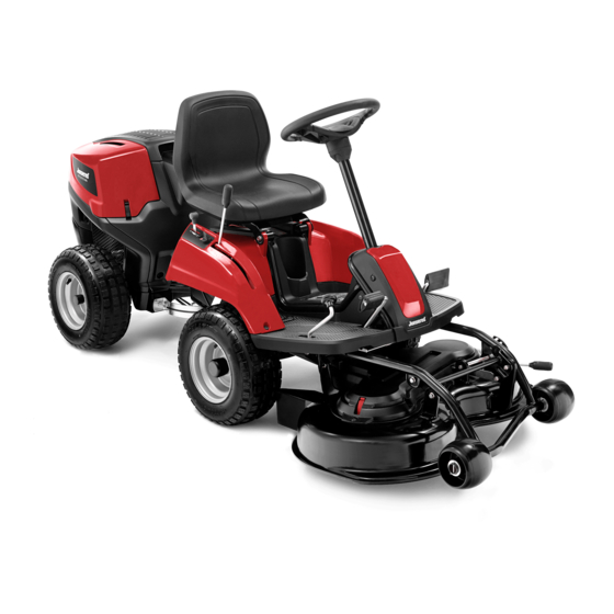
- Page 1 FR2315 MA Oper ator′ s manual Please read the oper ator’s manual carefully and make sure you understand the instructions before using the machine.
-
Page 2: Table Of Contents
CONTENTS Contents Removing the Mulching plug ........Lubrication CONTENTS Checking the engine’s oil level........Contents ..............Replacing the engine oil ..........INTRODUCTION Lubricating the front wheel bearings ......Dear Customer, ............General lubrication ............Driving and transport on public roads ......Troubleshooting schedule Towing ................ -
Page 3: Introduction
Dear Customer, Thank you for choosing a Jonsered Frontrider. Jonsered Frontriders are built to a unique design with a front-mounted cutting unit and a patented rear-wheel steering system. FrontRiders are designed for maximum efficiency even in small or confined areas. The closely grouped controls and pedal-operated hydrostatic transmission also contribute to the performance of this machine. -
Page 4: Service Journal
Service journal Pre-delivery service 1 Charge the battery for 4 hours at max. 3 amp. 2 Fit steering wheel, seat and any optional equipment. 3 Check and adjust tyre pressure. (60 kPa, 0.6 bar, 9 psi). 4 Check that the right amount of oil is in the engine. 5 Make sure the battery is connected. -
Page 5: Key To Symbols
KEY TO SYMBOLS Symbols Clutch out These symbols are on the machine and in the instructions. Parking brake WARNING! Careless or incorrect use can result in serious or fatal injury to the operator or others. Brake Please read the operator’s manual carefully and make sure you understand the instructions before using the machine. -
Page 6: Safety Instructions
SAFETY INSTRUCTIONS Safety instructions • Look out for the ejector and do not direct it towards anyone. These instructions are for your safety. Read them carefully. • Stop the engine and prevent it from starting before you clean the cutting unit. Insure your Rider •... -
Page 7: Driving On Slopes
SAFETY INSTRUCTIONS This is what you do • Never allow children or other persons not trained in the use of the machine to use or service it. Local laws may • Remove obstacles such as stones, branches, etc. regulate the age of the user. •... -
Page 8: Children
SAFETY INSTRUCTIONS • Never remove the fuel cap and fill the fuel tank when the IMPORTANT INFORMATION engine is running. Wheel weights fitted on the rear wheels are recommended • Allow the engine to cool before refuelling. Do not smoke. when driving on slopes for safer steering and improved Do not fill with fuel in the vicinity of sparks or naked manoeuvrability. -
Page 9: Transport
SAFETY INSTRUCTIONS • Take care with battery maintenance. Explosive gases • Reduce the risk of fire by removing grass, leaves and form in the battery. Never perform maintenance on the other debris that may have fastened on the machine. battery while smoking or in the vicinity of open flames or Allow the machine to cool before putting it in storage. -
Page 10: What Is What
WHAT IS WHAT? 9 10 Location of the controls 1 Product and serial number plate 8 Speed limiter for driving forward 2 Lever to disengage the drive 9 Cutting height adjustment lever 3 Battery 10 Parking brake 4 Throttle control/choke control 11 Lock button for parking brake 5 Ignition lock 12 Seat adjustment. -
Page 11: Presentation
PRESENTATION Presentation Speed limiter The speed of the machine is steplessly regulated with two Congratulations on your choice of an excellent quality product pedals. Pedal (1) is used to drive forwards, and pedal (2) to that will give you great pleasure for many years. drive backwards. -
Page 12: Cutting Height Adjustment Lever
PRESENTATION Cutting height adjustment lever Release lever The cutting height can be adjusted to 5 (1-5) different The release control must be pulled out in order for the positions with the cutting height lever. machine to be moved when the engine is shutoff. Pull the controls to the end positions, do not use an intermediate position. -
Page 13: Driving
Driving Before starting 3 Activate the parking brake. This is done as follows: IMPORTANT INFORMATION The air intake grille in the engine cover behind the driver’s seat must not be blocked by, for example, clothing, leaves, grass or dirt. Impaired cooling of the engine. Risk of major engine damage. -
Page 14: Starting The Engine With A Weak Battery
Driving • Finally the RED cable from both batteries. WARNING! Never run the engine indoors, in enclosed or poorly ventilated areas. The exhaust fumes contain toxic carbon IMPORTANT INFORMATION Never use a boost charger/ monoxide. start booster. Use only conventional battery chargers. Always disconnect the charger before starting the engine. -
Page 15: Cutting Tips
Driving Cutting tips Stop the engine Preferably allow the engine to idle for a minute to obtain WARNING! Clear the lawn from stones and normal working temperature before stopping it if it has been working hard. Avoid idling the engine for long periods, as other objects which can be thrown out by there is a risk of carbon build-up on the spark plugs. -
Page 16: Maintenance
Maintenance Maintenance schedule The following is a list of the maintenance which should be conducted on the machine. For those points not described in this manual, visit an authorised service workshop. Daily maintenance Maintenance interval in Maintenance At least once a year before starting hours Cleaning... -
Page 17: Cleaning
Maintenance Cleaning Belt Guard Release the clip and lift off the belt guard. Clean the machine directly after use. It is much easier to wash off grass cuttings before they dry. Checking and adjusting the steering wires Oily dirt can be removed using a cold degreasing agent. The steering is controlled by means of wires. -
Page 18: Checking The Parking Brake
Maintenance Checking the parking brake 3 Pull back the throttle to the full throttle position and check that the choke is no longer actuated. Check that the brake is correctly adjusted by placing the machine on a slight downhill slope with the clutch disengaged and activating the brake. -
Page 19: Replacement Of Fuel Filter
Maintenance Replacement of fuel filter Ignition system Replace the fuel filter every 100 running hours (once per The engine is equipped with an electronic ignition system. season) or more frequently if it is clogged. Only the spark plug requires maintenance. For recommended spark plug, see Technical data. -
Page 20: Check The Safety System
Maintenance Type: Flat pin, 15 A. WARNING! The cooling air intake rotates when the engine is running. Mind your fingers. Service position for the cutting unit The cutting deck can be removed in order to facilitate cleaning and servicing. IMPORTANT INFORMATION Avoid cutting when the cutting head is placed in service Do not use any other type of fuse when replacing. -
Page 21: Fitting The Cutting Head
Maintenance Fitting the cutting head 7 Lift of the drive belt. 8 Grip the top tubular construction of the unit and pull out 1 Make sure the lock is in upright position. the unit until it stops. 2 Place the belt under the stay of the cutting deck. 9 Make sure the lock is in upright position. -
Page 22: Checking The Blades
Maintenance Checking the blades 6 Push the deck until you feel the pipes touch bottom. To achieve the best mowing results it is important that the blades are undamaged and well-sharpened. Check that the blades’ attachment screws are tight. • Put the unit in the service position, see Service position for the cutting unit. -
Page 23: Replacing The Blades
Maintenance Replacing the blades Removing the Mulching plug • Put the unit in the service position, see Service position To change a Combi deck from the Mulching function to a for the cutting unit. cutting deck with rear ejection, remove the Mulching plug, which is located under the unit, attached with a screws. -
Page 24: Lubrication
Lubrication Checking the engine’s oil level. 4 Fit the drain plug and tighten it. 5 Fill the oil slowly. The oil is topped up through the hole the Check the oil level in the engine when the Rider stands dipstick sits in. See Checking the engine’s oil level for horizontal with the engine switched off. -
Page 25: Troubleshooting Schedule
Troubleshooting schedule Problem Cause Engine does not start There is no fuel in the fuel tank Faulty spark plug. Defective ignition cable. Dirt in the carburettor or fuel line Starter motor does not turn over the engine Defect safety switch Starter motor does not turn over the engine Battery flat Bad contact between the cable and battery Lift lever for cutting unit in wrong position... -
Page 26: Storage
Storage Winter storage Guard At the end of the season, or if the machine is going to stand There is a cover to protect your machine during storage or idle for more than 30 days, it should immediately be made transport. -
Page 27: Technical Data
TECHNICAL DATA FR2315 MA Dimensions Length with cutting unit, cm/inch 229 / 90,2 Width with cutting unit, cm/inch 99 / 39 Height, cm/in 108 / 42.7 Operating weight with cutting deck, kg/lb 215/474 Wheel base, cm/in 84,5 / 33,3 Tyre dimensions... -
Page 28: Ec Declaration Of Conformity
EC Declaration of Conformity (Applies to Europe only) Husqvarna AB, SE-561 82 Huskvarna, Sweden, tel.: +46-36-146500, hereby declares that Jonsered FR2315 MA from 2014’s serial numbers and onwards (the year is clearly stated in plain text on the rating plate with subsequent serial number), complies with the requirements of the COUNCIL’S DIRECTIVE:... - Page 32 Original instructions 1156464-26 ´®z+XNJ¶6M¨ ´®z+XNJ¶6M¨ 2013-10-25...
Need help?
Do you have a question about the Frontrider FR2315 MA and is the answer not in the manual?
Questions and answers
Klipparen startar bra men dör när jag gasar
The Jonsered FR2315 MA trimmer may start well but die when accelerating due to running the engine at low speed with the cutting blades engaged. The manual advises applying full throttle first when the cutting unit is in the mowing position to ensure proper operation. Not doing so can lead to poor engine performance or stalling when accelerating.
This answer is automatically generated