
Related Manuals for Jonsered FR2318 FA4X4


Summary of Contents for Jonsered FR2318 FA4X4
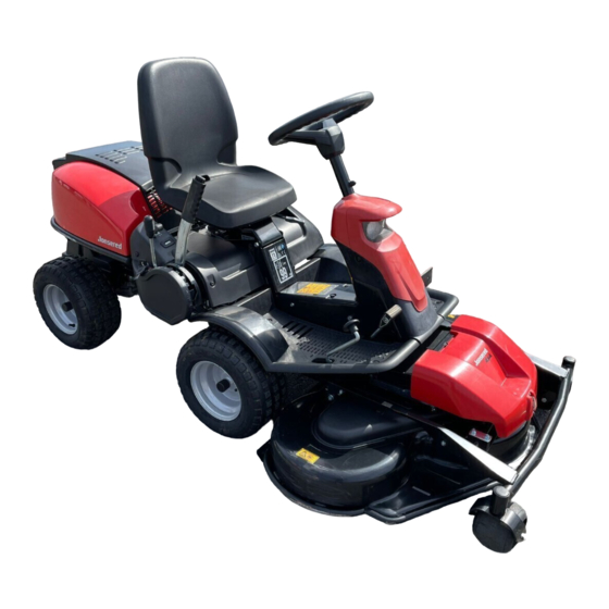
- Page 1 Oper ator ′ s manual Please read the oper ator’s manual carefully and make sure you understand the instructions before using the machine. FR 2318 F A FR 2318 FA 4X4...
-
Page 2: Table Of Contents
CONTENTS Contents Checking and adjustment of the cutting unit’s ground pressure ............... CONTENTS Checking the cutting unit’s parallelism ......Contents ..............Adjusting the parallelism of the cutting unit ....INTRODUCTION Service position for the cutting unit ......Dear Customer, ............Fitting the cutting head .......... -
Page 3: Introduction
Dear Customer, Thank you for choosing a Jonsered Frontrider. Jonsered Frontriders are built to a unique design with a front-mounted cutting unit and a patented rear-wheel steering system. FrontRiders are designed for maximum efficiency even in small or confined areas. The closely grouped controls and pedal-operated hydrostatic transmission also contribute to the performance of this machine. -
Page 4: Service Journal
Service journal Pre-delivery service 13 Tell customer about: Needs and benefits of following the service 1 Charge the battery for 4 hours at max. 3 amp. schedule. 2 Fit steering wheel, seat and any optional Servicing and the influence of this journal on the equipment. -
Page 5: Key To Symbols
KEY TO SYMBOLS Symbols Hydrostatic freewheel These symbols are on the machine and in the instructions. WARNING! Careless or incorrect use can Watch your hands and other body parts result in serious or fatal injury to the so they do not get caught and crushed operator or others. - Page 6 KEY TO SYMBOLS Starting instructions Check the engine’s oil level Check the hydrostat’s oil level Lift up the cutting unit Apply and lock the parking brake. If the engine is cold, use the choke Release the parking brake before driving 6 –...
-
Page 7: What Is What
WHAT IS WHAT? Location of the controls 1 Throttle control/choke control 9 Product and serial number plate 2 Ignition lock 10 Seat adjustment. 3 Cutting height adjustment lever 11 Lever to disengage the driving front axle FR 2318FA 4x4 4 Lifting lever for the cutting unit 12 Fuel cap 5 Speed limiter for reversing 13 Cover lock... -
Page 8: Safety Instructions
SAFETY INSTRUCTIONS Safety instructions • Remember that the driver is responsible for dangers or accidents. These instructions are for your safety. Read them carefully. • Never carry passengers. The machine is only intended to be used by one person. Insure your Rider •... -
Page 9: Driving On Slopes
SAFETY INSTRUCTIONS Driving on slopes • Never allow children or other persons not trained in the use of the machine to use or service it. Local laws may regulate the age of the user. Driving on slopes is one of the operations where the risk of the driver losing control of the machine or of it overturning is the greatest;... -
Page 10: Children
SAFETY INSTRUCTIONS Maintenance • Do not try to stabilize the machine by putting your foot on the ground. • Stop the engine. Prevent the engine from starting by • When cleaning the chassis, the machine may never be removing the ignition key before making any adjustments driven near verges or ditches. -
Page 11: Transport
SAFETY INSTRUCTIONS • Take care with battery maintenance. Explosive gases • Reduce the risk of fire by removing grass, leaves and form in the battery. Never perform maintenance on the other debris that may have fastened on the machine. battery while smoking or in the vicinity of open flames or Allow the machine to cool before putting it in storage. -
Page 12: Presentation
PRESENTATION Presentation Cutting unit Congratulations on your choice of an excellent quality product FR 2318FA and FR 2318FA 4x4 can be equipped with two that will give you great pleasure for many years. FR 2318 FA different cutting units. 4X4 is equipped with all wheel drive. •... -
Page 13: Cutting Height Adjustment Lever
PRESENTATION Cutting height adjustment lever Release lever The cutting height can be adjusted to 7 different positions with The release control must be pulled out in order for the the cutting height lever. machine to be moved when the engine is shutoff. Combi-unit 40-90 mm (1 9/16”... -
Page 14: Driving
Driving Before starting Start the engine • Read the safety instructions and information concerning 1 Make sure that the clutch control is depressed. FR 2216 the placement of controls and functions before starting. MA 4X4 has one control for the front axle and one control for the rear axle. -
Page 15: Starting The Engine With A Weak Battery
Driving Starting the engine with a weak With a warm engine: 5 Move the throttle in between positions 1 and 2. battery WARNING! Lead-acid batteries produce explosive gases. Avoid sparks, open flames and smoking close to batteries. Always wear protective glasses in the vicinity of batteries. If the battery is too weak to start the engine, it should be recharged. -
Page 16: Driving The Rider
Driving Driving the Rider Stop the engine 1 Release the parking brake by first pressing down the Always park the machine on a level surface with the engine parking brake pedal and then releasing it. OFF. 1 Lift up the cutting unit by pulling the lever backwards to its locked position. -
Page 17: Maintenance
Maintenance Maintenance schedule The following is a list of the maintenance which should be conducted on the machine. For those points not described in this manual, visit an authorised service workshop. Daily At least once a Maintenance interval Maintenance maintenance year in hours before starting... -
Page 18: Cleaning
Maintenance Cleaning Removing of the machine hoods Clean the machine directly after use. It is much easier to wash Engine cover off grass cuttings before they dry. The engine becomes accessible for service when the engine cover is opened. Fold the seat forward, loosen the snap lock under the seat and fold the cover backwards. -
Page 19: Muffler
Maintenance Muffler 2 Check the tension of the steering wires by pushing them together (at the arrows). It should be possible to push them together so that the distance between them is half as Check regularly that the muffler is complete and secured much, without using unnecessary force. -
Page 20: Adjusting The Parking Brake
Maintenance Adjusting the parking brake Adjusting the throttle wire Check that the parking brake is adjusted correctly by placing The throttle cable may need to be adjusted, if the engine does the machine on a slope with the front and rear axles not respond as it should when accelerating, if it produces disengaged. -
Page 21: Replacing The Air Filter
Maintenance Replacing the air filter Checking the fuel pump’s air filter If the engine seems to lack power or does not run smoothly Check regularly that the fuel pump’s air filter is free from dirt. this may be because the air filter is clogged. It is therefore The filter can when necessary be cleaned with a brush. -
Page 22: Check The Safety System
Maintenance Check the safety system Checking the tyre pressure The machine is equipped with a safety system that prevents The tyre pressure should be 60 kPa (0.6 bar / 9 PSI) all round. starting or driving under the following conditions. To improve driving the pressure on the rear tyres can be The engine can only be started when: reduced to 40 kPa (0.4 bar/5.6 PSI). -
Page 23: Checking And Adjustment Of The Cutting Unit's Ground Pressure
Maintenance Checking and adjustment of the Adjusting the parallelism of the cutting unit’s ground pressure cutting unit To achieve the best cutting results the cutting unit should 1 Remove the front hood and right-hand fender. follow the underlying surface without pressing too hard 2 Unscrew the belt shield. -
Page 24: Service Position For The Cutting Unit
Maintenance Service position for the cutting unit 5 Remove the drive belt and place it in the belt holder. The cutting head can be placed in the service position to provide easy access for cleaning, repairs and servicing. In the service position the cutting unit is raised and locked in the vertical position. -
Page 25: Fitting The Cutting Head
Maintenance Fitting the cutting head 6 Lift up the cutting unit WARNING! Wear protective glasses when fitting the cutting unit. The spring which tensions up the belt may break and cause personal injury. 1 Position the machine on flat ground. Apply the parking brake. -
Page 26: Removing The Cutting Unit
Maintenance Removing the cutting unit Replacing the blades • Put the unit in the service position, see Service position 1 Carry out points 1-6 to put the cutting unit in the service for the cutting unit. position, see Service position for the cutting unit. •... -
Page 27: Lubrication
Lubrication Checking the engine’s oil level. Replacing the engine oil Check the oil level in the engine when the Rider stands The engine oil should be changed the first time after 8 hours horizontal with the engine switched off. Do not check the oil running time. -
Page 28: Checking The Transmission Oil Level
Troubleshooting schedule Checking the transmission oil level 3 Screw on the belt shield. 1 Remove the transmission cover. Undo the two screws (one on each side) and lift off the transmission cover. With daily use, lubrication should be carried out twice weekly. General lubrication All joints and bearings are lubricated using molybdenum disulphide grease during manufacture. - Page 29 Troubleshooting schedule Problem Cause There is no fuel in the fuel tank Spark plug defective Engine does not start Faulty spark plug connections or interchanged cables Dirt in the carburettor or fuel line Dirt in the carburettor or fuel line Battery flat Bad contact between the cable and battery Lift lever for cutting unit in wrong position...
-
Page 30: Storage
Storage Winter storage Guard At the end of the season, or if the machine is going to stand There is a cover to protect your machine during storage or idle for more than 30 days, it should immediately be made transport. -
Page 31: Technical Data
TECHNICAL DATA FR 2318FA FR 2318FA 4x4 Dimensions Length without cutting unit, mm/ft 2020/6,61 2020/6,61 Width without cutting unit, mm/ft 890/2,92 890/2,92 Height, mm/ft 1150/3,77 1150/3,77 Machine without cutting unit, with empty tanks, kg/lb 231 / 509 243 / 536 Wheel base, mm/ft 887/2,9 887/2,9... -
Page 32: Ec Declaration Of Conformity
EC Declaration of Conformity (Applies to Europe only) Husqvarna AB, SE-561 82 Huskvarna, Sweden, tel.: +46-36-146500, hereby declares that Jonsered FR 2318FA and FR 2318FA 4X4 from 2014’s serial numbers and onwards (the year is clearly stated in plain text on the rating plate with subsequent serial number), complies with the requirements of the COUNCIL’S DIRECTIVE:... - Page 36 Original instructions 1156992-26 ´®z+X•6¶6w¨ ´®z+X•6¶6w¨ 2014-07-01...
Need help?
Do you have a question about the FR2318 FA4X4 and is the answer not in the manual?
Questions and answers