Table of Contents
Advertisement
Quick Links
IMB-Q670 Micro-ATX Motherboard
IEI Technology Corp.
MODEL:
IMB-Q670
Micro-ATX LGA1155 Motherboard for Intel® Core™ i7/i5 Quad
Core or i3 Dual Core CPU, Intel® Q67, DDR3, VGA/DVI-D/HDMI
Dual Intel PCIe GbE, Two USB 3.0 ports, Ten COM ports
Two SATA 6Gb/s ports, HD Audio and RoHS
Rev. 2.01 – July 10, 2012
User Manual
Page i
Advertisement
Table of Contents

Related Manuals for IEI Technology IMB-Q670


Summary of Contents for IEI Technology IMB-Q670
-
Page 1: User Manual
IMB-Q670 Micro-ATX Motherboard IEI Technology Corp. MODEL: IMB-Q670 Micro-ATX LGA1155 Motherboard for Intel® Core™ i7/i5 Quad Core or i3 Dual Core CPU, Intel® Q67, DDR3, VGA/DVI-D/HDMI Dual Intel PCIe GbE, Two USB 3.0 ports, Ten COM ports Two SATA 6Gb/s ports, HD Audio and RoHS... - Page 2 IMB-Q670 Micro-ATX Motherboard Revision Date Version Changes July 10, 2012 2.01 Modified Appendix C: Digital I/O Interface Modified RS-422/485 connector pinouts November 24, 2011 2.00 Modified for R20 version August 16, 2011 1.02 Modified Section 4.3.1: AT/ATX Power Mode Jumper Added Section 4.6: Intel®...
- Page 3 IMB-Q670 Micro-ATX Motherboard Copyright COPYRIGHT NOTICE The information in this document is subject to change without prior notice in order to improve reliability, design and function and does not represent a commitment on the part of the manufacturer. In no event will the manufacturer be liable for direct, indirect, special, incidental, or consequential damages arising out of the use or inability to use the product or documentation, even if advised of the possibility of such damages.
-
Page 4: Table Of Contents
PTIONAL TEMS 3 CONNECTORS ......................14 3.1 P ..............15 ERIPHERAL NTERFACE ONNECTORS 3.1.1 IMB-Q670 Layout .................... 15 3.1.2 Peripheral Interface Connectors ..............15 3.1.3 External Interface Panel Connectors............... 16 3.2 I ..............17 NTERNAL ERIPHERAL ONNECTORS 3.2.1 ATX Power Connector ..................17 3.2.2 Battery Connector.................... - Page 5 IMB-Q670 Micro-ATX Motherboard 3.2.11 PCH Fan Connector..................27 3.2.12 PCI Express Power ..................28 3.2.13 SATA 3Gb/s Drive Connector ................ 29 3.2.14 SATA 6Gb/s Drive Connector ................ 30 3.2.15 Serial Port Connector, RS-422/485..............31 3.2.16 Serial Port Connectors, RS-232..............32 3.2.17 SMBus Connector ..................
- Page 6 IMB-Q670 Micro-ATX Motherboard 4.5.1 Audio Connector ....................61 4.5.2 LAN Connection....................62 4.5.3 Parallel Device Connection................63 4.5.4 PS/2 Keyboard and Mouse Connection ............64 4.5.5 Serial Device Connection ................65 4.5.6 USB Connection (Dual Connector) ..............66 4.5.7 VGA Monitor Connection ................67 ®...
- Page 7 IMB-Q670 Micro-ATX Motherboard 5.3.10 Serial Port Console Redirection ..............99 5.3.11 IEI Feature ....................100 5.4 C ......................... 101 HIPSET 5.4.1 Northbridge Configuration ................103 5.4.2 Southbridge Configuration ................105 5.4.3 Integrated Graphics ..................109 5.4.4 ME Subsystem ....................111 5.5 B...
- Page 8 IMB-Q670 Micro-ATX Motherboard E.2 C ..................161 OMPATIBLE ROCESSORS F HAZARDOUS MATERIALS DISCLOSURE............162 F.1 H IPB P AZARDOUS ATERIALS ISCLOSURE ABLE FOR RODUCTS ERTIFIED AS HS C 2002/95/EC W ........163 OMPLIANT NDER ITHOUT ERCURY Page viii...
- Page 9 IMB-Q670 Micro-ATX Motherboard List of Figures Figure 1-1: IMB-Q670........................2 Figure 1-2: Connectors ........................4 Figure 1-3: IMB-Q670 Dimensions (mm) ..................5 Figure 1-4: Data Flow Diagram......................6 Figure 3-1: Connectors and Jumpers..................15 Figure 3-2: ATX/AT Power Connector Pinout Location ............18 Figure 3-3: Battery Connector Location..................19 Figure 3-4: CPU Fan Connector Location ..................20...
- Page 10 IMB-Q670 Micro-ATX Motherboard Figure 3-27: VGA Connector .......................45 Figure 4-1: Intel LGA1155 Socket ....................50 Figure 4-2: Remove Protective Cover..................51 Figure 4-3: CPU Socket Load Plate.....................51 Figure 4-4: Insert the Socket LGA1155 CPU................52 Figure 4-5: Cooling Kits (CF-1156A-RS and CF-1156B-RS) .............53 Figure 4-6: DIMM Installation.......................54...
- Page 11 IMB-Q670 Micro-ATX Motherboard Figure 6-15: LAN Driver License Agreement ................127 Figure 6-16: LAN Driver Setup Options................... 128 Figure 6-17: LAN Driver Installation ..................128 Figure 6-18: LAN Driver Installation Complete............... 129 Figure 6-19: Audio Driver – Extracting Files................130 Figure 6-20: Audio Driver Welcome Screen................
- Page 12 IMB-Q670 Micro-ATX Motherboard List of Tables Table 1-1: IMB-Q670 Specifications....................8 Table 2-1: Packing List.........................12 Table 2-2: Optional Items......................13 Table 3-1: Peripheral Interface Connectors ................16 Table 3-2: Rear Panel Connectors ....................17 Table 3-3: ATX/AT Power Connector Pinouts................18 Table 3-4: Battery Connector Pinouts ..................19 Table 3-5: CPU Fan Connector Pinouts..................20...
- Page 13 IMB-Q670 Micro-ATX Motherboard Table 3-28: HDMI Connector Pinouts ..................43 Table 3-29: Serial Port Connector Pinouts ................44 Table 3-30: VGA Connector Pinouts...................45 Table 3-31: DVI Connector Pinouts.....................46 Table 4-1: Jumpers ........................55 Table 4-2: AT/ATX Power Mode Jumper Settings ..............56 Table 4-3: Clear BIOS Jumper Settings..................57 Table 4-4: ME Debug Connector Pinouts ...................58...
- Page 14 BIOS Menu 14: FAN 2 Configuration ..................93 BIOS Menu 15: Secondary Super IO Configuration ..............94 BIOS Menu 16: Serial Port Console Redirection ...............99 BIOS Menu 17: IEI Feature......................101 BIOS Menu 18: Chipset ......................102 BIOS Menu 19: Northbridge Chipset Configuration............... 103 BIOS Menu 20: Southbridge Chipset Configuration ..............
-
Page 15: Introduction
IMB-Q670 Micro-ATX Motherboard Chapter Introduction Page 1... -
Page 16: Introduction
240-pin 1333/1066 MHz dual-channel DDR3 DIMM modules up to 32.0 GB maximum. The IMB-Q670 includes a VGA, HDMI, and DVI-D port. Expansion and I/O include one PCI slot, one PCIe x16 slot, one PCIe x4 slot, one PCIe x1 slot, two USB 3.0 ports on the rear panel by NEC D720200F1, two USB 2.0 on the rear... -
Page 17: Features
IMB-Q670 Micro-ATX Motherboard 1.3 Features Some of the IMB-Q670 motherboard features are listed below: Micro-ATX RoHS compliant LGA1155 CPU socket One PCI card expansion slot One PCIe x16 card expansion slot One PCIe x1 card expansion slot One PCIe x4 card expansion slot... -
Page 18: Connectors
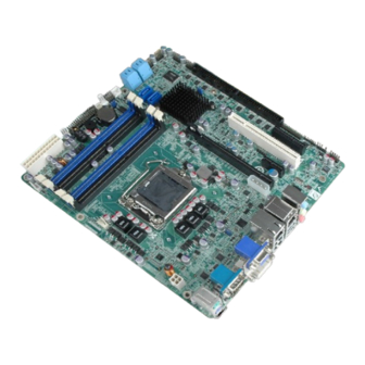
IMB-Q670 Micro-ATX Motherboard 1.4 Connectors The connectors on the IMB-Q670 are shown in the figure below. Figure 1-2: Connectors Page 4... -
Page 19: Dimensions
IMB-Q670 Micro-ATX Motherboard 1.5 Dimensions The main dimensions of the IMB-Q670 are shown in the diagram below. Figure 1-3: IMB-Q670 Dimensions (mm) Page 5... -
Page 20: Data Flow
IMB-Q670 Micro-ATX Motherboard 1.6 Data Flow F igure 1-4 shows the data flow between the system chipset, the CPU and other components installed on the motherboard. Figure 1-4: Data Flow Diagram Page 6... -
Page 21: Technical Specifications
IMB-Q670 Micro-ATX Motherboard 1.7 Technical Specifications IMB-Q670 technical specifications are listed below. Specification/Model IMB-Q670 Micro-ATX Form Factor LGA1155 Socket Intel® Core™ i7/i5/i3 Quad/Dual core CPU Supported Intel® Q67 Northbridge Chipset Integrated Graphics Supports DirectX 10.1/OpenGL 3.0 Full MPEG2, VC1, AVC Decode... -
Page 22: Table 1-1: Imb-Q670 Specifications
(Intel® 2.60GHz CPU with 1333MHz DDR3 4GB x 4 Memory) -20ºC ~ 60ºC/-4°F ~ 140°F Operating temperature Humidity 5% ~ 95% (non-condensing) Physical Specifications Dimensions 244 mm x 244 mm Weight GW/NW 1200 g / 680 g Table 1-1: IMB-Q670 Specifications Page 8... -
Page 23: Packing List
IMB-Q670 Micro-ATX Motherboard Chapter Packing List Page 9... -
Page 24: Anti-Static Precautions
Only handle the edges of the PCB: Don't touch the surface of the motherboard. Hold the motherboard by the edges when handling. 2.2 Unpacking Precautions When the IMB-Q670 is unpacked, please do the following: Follow the antistatic guidelines above. Make sure the packing box is facing upwards when opening. -
Page 25: Packing List
NOTE: If any of the components listed in the checklist below are missing, do not proceed with the installation. Contact the IEI reseller or vendor the IMB-Q670 was purchased from or contact an IEI sales representative directly by sending an email to ales@iei.com.tw. -
Page 26: Optional Items
IMB-Q670 Micro-ATX Motherboard Quantity Item and Part Number Image Quick Installation Guide Table 2-1: Packing List 2.4 Optional Items The following are optional components which may be separately purchased: Item and Part Number Image Dual Ports USB Cable with Bracket... -
Page 27: Table 2-2: Optional Items
IMB-Q670 Micro-ATX Motherboard Item and Part Number Image 20-Pin INFINEON TPM Module, S/W management tool (P/N: TPM-IN01-R10) Table 2-2: Optional Items Page 13... -
Page 28: Connectors
IMB-Q670 Micro-ATX Motherboard Chapter Connectors Page 14... -
Page 29: Peripheral Interface Connectors
IMB-Q670 Micro-ATX Motherboard 3.1 Peripheral Interface Connectors This chapter details all the jumpers and connectors. 3.1.1 IMB-Q670 Layout The figures below show all the connectors and jumpers. Figure 3-1: Connectors and Jumpers 3.1.2 Peripheral Interface Connectors The table below lists all the connectors on the board. -
Page 30: External Interface Panel Connectors
IMB-Q670 Micro-ATX Motherboard Connector Type Label CPU fan 4-pin wafer CPU_FAN CPU power 4-pin box header CPU12V1 Digital I/O 26-pin header DIO1 Front panel audio 10-pin header FP_AUDIO Front panel 14-pin header F_PANEL1 FW programming 8-pin header Infrared interface 5-pin header... -
Page 31: Internal Peripheral Connectors
VGA and DVI connector 15-pin female, DVI+CRT 24-pin header Table 3-2: Rear Panel Connectors 3.2 Internal Peripheral Connectors The section describes all of the connectors on the IMB-Q670. 3.2.1 ATX Power Connector CN Label: CN Type: 24-pin ATX (2x12) CN Location:... -
Page 32: Battery Connector
IMB-Q670 Micro-ATX Motherboard Figure 3-2: ATX/AT Power Connector Pinout Location Description Description +3.3 V +3.3V +3.3 V -12V +5 V IO_PS_ON- +5 V PWRGD_PS +5 VSB +5 V +12 V +5 V +12 V +5 V +3.3 V Table 3-3: ATX/AT Power Connector Pinouts 3.2.2 Battery Connector... -
Page 33: Cpu Fan Connector
IMB-Q670 Micro-ATX Motherboard CN Location: See Figure 3-3 CN Pinouts: See Table 3-4 This is connected to the system battery. The battery provides power to the system clock to retain the time when power is turned off. Figure 3-3: Battery Connector Location... -
Page 34: Cpu Power Connector
IMB-Q670 Micro-ATX Motherboard The fan connector attaches to a CPU cooling fan. Figure 3-4: CPU Fan Connector Location PIN NO. DESCRIPTION +12 V FANIN FANOUT Table 3-5: CPU Fan Connector Pinouts 3.2.4 CPU Power Connector CN Label: CPU12V1 4-pin box header... -
Page 35: Digital I/O Connector
IMB-Q670 Micro-ATX Motherboard Figure 3-5: CPU Power Connector Location PIN NO. DESCRIPTION +12V +12V Table 3-6: CPU Power Connector Pinouts 3.2.5 Digital I/O Connector CN Label: DIO1 CN Type: 26-pin header CN Location: See Figure 3-6 CN Pinouts: See Table 3-7 The digital I/O connector provides programmable input and output for external devices. -
Page 36: Front Panel Audio Connector
IMB-Q670 Micro-ATX Motherboard Figure 3-6: Digital I/O Connector Location PIN NO. DESCRIPTION PIN NO. DESCRIPTION D_IN0 D_OUT0 D_IN1 D_OUT1 D_IN2 D_OUT2 D_IN3 D_OUT3 D_8IN0 D_8OUT0 D_8IN1 D_8OUT1 D_8IN2 D_8OUT2 D_8IN3 D_8OUT3 D_8IN4 D_8OUT4 D_8IN5 D_8OUT5 D_8IN6 D_8OUT6 D_8IN7 D_8OUT7 Table 3-7: Digital I/O Connector Pinouts 3.2.6 Front Panel Audio Connector... -
Page 37: Front Panel Connector
IMB-Q670 Micro-ATX Motherboard CN Pinouts: See Table 3-8 This connector connects to speakers, a microphone and an audio input. Figure 3-7: Front Panel Audio Connector Location Description Description MIC_L Audio GND MIC_R FP_AUO DETECT Line_R Audio GND F_SENSE Line_L Audio GND Table 3-8: Front Panel Audio Connector Pinouts 3.2.7 Front Panel Connector... -
Page 38: Fw Programming
IMB-Q670 Micro-ATX Motherboard Figure 3-8: Front Panel Connector Location FUNCTION DESCRIPTION FUNCTION DESCRIPTION Power LED Power LED Speaker Beep Power Power Button PWRBTSW# PC Beep Reset HDD LED HDDLED EXTRST# HDDLED# Table 3-9: Front Panel Connector Pinouts 3.2.8 FW Programming... -
Page 39: Infrared Interface Connector
IMB-Q670 Micro-ATX Motherboard Figure 3-9: FW Programming Connector Location Description Description +3.3V Table 3-10: FW Programming Connector Pinouts 3.2.9 Infrared Interface Connector CN Label: CN Type: 5-pin header (1x5) CN Location: See Figure 3-10 CN Pinouts: See Table 3-11 The infrared connector attaches to an infrared receiver for use with remote controls. -
Page 40: Memory Card Slot
IMB-Q670 Micro-ATX Motherboard Figure 3-10: Infrared Connector Location Description IR_RX IR_TX Table 3-11: Infrared Connector Pinouts 3.2.10 Memory Card Slot CN Label: DIMM1, DIMM2 CN Type: DDR3 DIMM slot CN Location: F igure 3-11 The DIMM slots are for DIMM memory modules. -
Page 41: Pch Fan Connector
IMB-Q670 Micro-ATX Motherboard Figure 3-11: Memory Card Slot Location 3.2.11 PCH Fan Connector CN Label: PCH_FAN CN Type: 3-pin header CN Location: See Figure 3-12 CN Pinouts: See Table 3-12 The PCH fan connector attaches to a PCH cooling fan. -
Page 42: Pci Express Power
IMB-Q670 Micro-ATX Motherboard Figure 3-12: PCH Fan Connector Location Description FANIN +12V Table 3-12: PCH Fan Connector Pinouts 3.2.12 PCI Express Power CN Label: PCIE_12V1 CN Type: 4-pin Molex CN Location: See Figure 3-13 CN Pinouts: See Table 3-13 Provides extra power to the PCIe x16 card. -
Page 43: Sata 3Gb/S Drive Connector
IMB-Q670 Micro-ATX Motherboard Figure 3-13: PCIe Power Location Description +5 V +12 V Table 3-13: PCIe Power Pinouts 3.2.13 SATA 3Gb/s Drive Connector CN Label: SATA34, SATA56 16-pin SATA connector CN Type: CN Location: See Figure 3-14 CN Pinouts: See Table 3-14 The SATA drive connectors can be connected to SATA drives. -
Page 44: Sata 6Gb/S Drive Connector
IMB-Q670 Micro-ATX Motherboard Figure 3-14: SATA 3Gb/s Drive Connector Location Description Description SATA20_PTX_DRX_P3/5 SATA20_PTX_DRX_P2/4 SATA20_PTX_DRX_N3/5 SATA20_PTX_DRX_N2/4 SATA20_PRX_DTXN3/5 SATA20_PRX_DTX_N2/4 SATA20_PRX_DTX_P3/5 SATA20_PRX_DTX_P2/4 Table 3-14: SATA 3Gb/s Drive Connector Pinouts 3.2.14 SATA 6Gb/s Drive Connector CN Label: SATA1, SATA2 CN Type: 7-pin SATA drive connectors... -
Page 45: Serial Port Connector, Rs-422/485
IMB-Q670 Micro-ATX Motherboard Figure 3-15: SATA 6Gb/s Drive Connector Location Description SATA30_PTX_DRX_P0/1 SATA30_PTX_DRX_N0/1 SATA30_PRX_DTX_N0/1 SATA30_PRX_DTX_P0/1 Table 3-15: SATA 6Gb/s Drive Connector Pinouts 3.2.15 Serial Port Connector, RS-422/485 CN Label: COM4 CN Type: 4-pin box header (1x4) CN Location: See Figure 3-16... -
Page 46: Serial Port Connectors, Rs-232
IMB-Q670 Micro-ATX Motherboard Figure 3-16: Serial Port Connector Location PIN NO. DESCRIPTION PIN NO. DESCRIPTION RXD422- RXD422+ TXD422+/TXD485+ TXD422-/TXD485- Table 3-16: Serial Port Connector Pinouts 3.2.16 Serial Port Connectors, RS-232 CN Label: COM2_3_5_6, COM7-10 40-pin box header (2x20) CN Type:... -
Page 47: Figure 3-17: Serial Port Connector Location
IMB-Q670 Micro-ATX Motherboard Figure 3-17: Serial Port Connector Location PIN NO. DESCRIPTION PIN NO. DESCRIPTION NDCD2/7# NDSR2/7# NRXD2/7 NRTS2/7# NTXD2/7 NCTS2/7# NDTR2/7# NRI2/7# NDCD3/8# NDSR3/8# NRXD3/8 NRTS3/8# NTXD3/8 NCTS3/8# NDTR3/8# NRI3/8# NDCD5/9# NDSR5/9# NRXD5/9 NRTS5/9# NTXD5/9# NCTS5/9# NDTR5/9# NRI5/9# NDCD6/10... -
Page 48: Smbus Connector
IMB-Q670 Micro-ATX Motherboard PIN NO. DESCRIPTION PIN NO. DESCRIPTION NDTR6/10# NRI6/10# Table 3-17: Serial Port Connector Pinouts 3.2.17 SMBus Connector CN Label: SMBUS_1 CN Type: 4-pin wafer CN Location: See Figure 3-18 CN Pinouts: See Table 3-18 The SMBus (System Management Bus) connector provides low-speed system management communications. -
Page 49: Spdif Connector
IMB-Q670 Micro-ATX Motherboard DESCRIPTION Table 3-18: SMBus Connector Pinouts 3.2.18 SPDIF Connector CN Label: SPDIF CN Type: 5-pin header CN Location: See Figure 3-19 CN Pinouts: See Table 3-19 Use the SPDIF connector to connect digital audio devices to the system. -
Page 50: Spi Connector
IMB-Q670 Micro-ATX Motherboard 3.2.19 SPI Connector CN Label: 8-pin header CN Type: CN Location: See Figure 3-20 CN Pinouts: See Table 3-20 The SPI connector is used to flash the BIOS. Figure 3-20: SPI Connector Location PIN NO. DESCRIPTION PIN NO. -
Page 51: Tpm Connector
IMB-Q670 Micro-ATX Motherboard CN Location: See Figure 3-21 CN Pinouts: See Table 3-21 The fan connector attaches to a cooling fan. Figure 3-21: System Fan Connector Location PIN NO. DESCRIPTION +12 V Table 3-21: System Fan Connector Pinouts 3.2.21 TPM Connector... -
Page 52: Usb Connectors
IMB-Q670 Micro-ATX Motherboard Figure 3-22: TPM Connector Location PIN NO. DESCRIPTION PIN NO. DESCRIPTION TPMCLK LPC_FRAME# BUF_PCIRST# LPC_AD3 LPC_AD2 +3.3V LPC_AD1 LPC_AD0 SMBCLK_RESUME SMBDATA_RESUME +3.3V_STBY SERIRQ +3.3V LPCPD_N LDRQ0# Table 3-22: TPM Connector Pinouts 3.2.22 USB Connectors CN Label: USB1, USB2, USB3, USB4... -
Page 53: Figure 3-23: Usb Connector Pinout Locations
IMB-Q670 Micro-ATX Motherboard The USB connectors connect to USB devices. Each pin header provides two USB ports. Figure 3-23: USB Connector Pinout Locations PIN NO. DESCRIPTION PIN NO. DESCRIPTION +USB_PWR USB20_C_N USB20_C_P USB20_C_P USB20_C_N +USB_PWR Table 3-23: USB Port Connector Pinouts... -
Page 54: External Peripheral Interface Connector Panel
IMB-Q670 Micro-ATX Motherboard 3.3 External Peripheral Interface Connector Panel The figure below shows the external peripheral interface connector (EPIC) panel. The EPIC panel consists of the following: Figure 3-24: External Peripheral Interface Connector 3.3.1 Audio Connector CN Label: AUDIO_JACK CN Type:... -
Page 55: Keyboard/Mouse Connector
IMB-Q670 Micro-ATX Motherboard Figure 3-25: Audio Connector 3.3.2 Keyboard/Mouse Connector CN Label: KBMS CN Type: Dual PS/2 CN Location: See Figure 3-24 See Table 3-24 CN Pinouts: The PS/2 ports are for connecting a PS/2 mouse and a PS/2 keyboard. -
Page 56: Ethernet And Usb Connector
IMB-Q670 Micro-ATX Motherboard 3.3.3 Ethernet and USB Connector CN Label: LAN1_USB, LAN2_USB RJ-45, USB CN Type: CN Location: See Figure 3-24 CN Pinouts: See Table 3-25, Table 3-26 and Table 3-27 The LAN connector connects to a local network. DESCRIPTION DESCRIPTION 1.9V_LAN1/... -
Page 57: Hdmi Port Connector
IMB-Q670 Micro-ATX Motherboard DESCRIPTION DESCRIPTION USB3P0_TXDP1_C USB_3P0_VCC2 USB2P0_DM2_L USB2P0_DP2_L USB3P0_RXDN2 USB3P0_RXDP2 USB3P0_TXDN2_C USB3P0_TXDP2_C Table 3-27: LAN2_USB Port Pinouts 3.3.4 HDMI Port Connector CN Label: HDMI HDMI connector CN Type: CN Location: See Figure 3-24 CN Pinouts: See Table 3-28 The HDMI port connects to an HDMI device. -
Page 58: Serial Port Connectors (Com1)
IMB-Q670 Micro-ATX Motherboard 3.3.5 Serial Port Connectors (COM1) CN Label: COM1 DB-9 connector CN Type: CN Location: See Figure 3-24 CN Pinouts: See Table 3-29 The serial port connects to a RS-232 serial communications device. PIN NO. DESCRIPTION PIN NO. -
Page 59: Figure 3-27: Vga Connector
IMB-Q670 Micro-ATX Motherboard DESCRIPTION DESCRIPTION CRT_RED CRT_GREEN CRT_BLUE +5V CRT CRT_PLUG# CRT_DDC_DATA CRT_HSYNC CRT_VSYNC CRT_DDC_CLK Table 3-30: VGA Connector Pinouts Figure 3-27: VGA Connector The DVI connector connects to a monitor that supports DVI video input. DESCRIPTION DESCRIPTION DVI_TMDS_C_DATA2# DVI_TMDS_C_DATA2... -
Page 60: Table 3-31: Dvi Connector Pinouts
IMB-Q670 Micro-ATX Motherboard DESCRIPTION DESCRIPTION DVI_TMDS_C_CLK DVI_TMDS_C_CLK# Table 3-31: DVI Connector Pinouts Page 46... -
Page 61: Installation
IMB-Q670 Micro-ATX Motherboard Chapter Installation Page 47... -
Page 62: Anti-Static Precautions
Electrostatic discharge (ESD) can cause serious damage to electronic components, including the IMB-Q670. Dry climates are especially susceptible to ESD. It is therefore critical that whenever the IMB-Q670 or any other electrical component is handled, the following anti-static precautions are strictly adhered to. - Page 63 This helps to prevent potential ESD damage. Turn all power to the IMB-Q670 off: When working with the IMB-Q670, make sure that it is disconnected from all power supplies and that no electricity is being fed into the system.
-
Page 64: Socket Lga1155 Cpu Installation
IMB-Q670 Micro-ATX Motherboard 4.2.1 Socket LGA1155 CPU Installation NOTE: To enable Hyper-Threading, the CPU and chipset must both support it. WARNING: CPUs are expensive and sensitive components. When installing the CPU please be careful not to damage it in anyway. Make sure the CPU is installed properly and ensure the correct cooling kit is properly installed. -
Page 65: Figure 4-2: Remove Protective Cover
IMB-Q670 Micro-ATX Motherboard Step 1: Remove the protective cover. The black protective cover can be removed by pulling up on the tab labeled "Remove". See Figure 4-2. Figure 4-2: Remove Protective Cover Step 2: Open the socket. Disengage the load lever by pressing the lever down and slightly outward to clear the retention tab. -
Page 66: Figure 4-4: Insert The Socket Lga1155 Cpu
IMB-Q670 Micro-ATX Motherboard Step 4: Orientate the CPU properly. The contact array should be facing the CPU socket. Step 5: Correctly position the CPU. Match the Pin 1 mark with the cut edge on the CPU socket. Step 6: Align the CPU pins. Locate pin 1 and the two orientation notches on the CPU. -
Page 67: Socket Lga1155 Cooling Kit Installation
ONLY compatible with captive screw type cooling fans. Figure 4-5: Cooling Kits (CF-1156A-RS and CF-1156B-RS) The cooling kit can be bought from IEI. The cooling kit has a heatsink and fan. WARNING: Do not wipe off (accidentally or otherwise) the pre-sprayed layer of thermal paste on the bottom of the heat sink. -
Page 68: Dimm Installation
Secure the cooling kit by fastening the four retention screws of the cooling kit. Step 5: Connect the fan cable. Connect the cooling kit fan cable to the fan connector on the IMB-Q670. Carefully route the cable and avoid heat generating chips and blades.Step 0: 4.2.3 DIMM Installation To install a DIMM, please follow the steps below and refer to Figure 4-6. -
Page 69: Jumper Settings
IMB-Q670 Micro-ATX Motherboard Step 4: Removing a DIMM. To remove a DIMM, push both handles outward. The memory module is ejected by a mechanism in the socket.Step 0: 4.3 Jumper Settings NOTE: A jumper is a metal bridge used to close an electrical circuit. -
Page 70: Clear Cmos Jumper
IMB-Q670 Micro-ATX Motherboard Jumper Location: See Figure 4-7 The AT/ATX Power Select jumper specifies the systems power mode as AT or ATX. Setting Description Closed ATX power (Default) Open AT power Table 4-2: AT/ATX Power Mode Jumper Settings Figure 4-7: AT/ATX Power Mode Jumper Location 4.3.2 Clear CMOS Jumper... -
Page 71: Me Debug Connector
IMB-Q670 Micro-ATX Motherboard Setting Description Clear BIOS Table 4-3: Clear BIOS Jumper Settings Figure 4-8: Clear BIOS Jumper Location 4.3.3 ME Debug Connector CN Label: J_FLASH1 CN Type: 3-pin header CN Location: See Figure 3-5 CN Pinouts: See Table 3-6 The ME Debug connector allows ME firmware overwrite protection. -
Page 72: Usb Power Select Jumper
IMB-Q670 Micro-ATX Motherboard Figure 4-9: ME Debug Connector Location PIN NO. DESCRIPTION Short 1-2 Overwrite disable Short 2-3 Overwrite enable Table 4-4: ME Debug Connector Pinouts 4.3.4 USB Power Select Jumper Jumper Label: USB_PWR1 3-pin header Jumper Type: Jumper Settings:... -
Page 73: Wake-On Lan Jumper
IMB-Q670 Micro-ATX Motherboard Figure 4-10: USB Power Select Jumper Location 4.3.5 Wake-on LAN Jumper CN Label: WOL_SEL1 CN Type: 3-pin header CN Location: See Figure 4-11 See Table 4-6 CN Pinouts: The Wake-on LAN connector allows the user to enable or disable the Wake-on LAN (WOL) function. -
Page 74: Internal Peripheral Device Connections
This section outlines the installation of peripheral devices to the onboard connectors. 4.4.1 SATA Drive Connection The IMB-Q670 is shipped with four SATA drive cables. To connect the SATA drives to the connectors, please follow the steps below. Step 1: Locate the connectors. -
Page 75: External Peripheral Interface Connection
This section describes connecting devices to the external connectors on the IMB-Q670. 4.5.1 Audio Connector The audio jacks on the external audio connector enable the IMB-Q670 to be connected to a stereo sound setup. Each jack supports both input and output. When connecting a device, the High Definition Audio utility will automatically detect input or output. -
Page 76: Lan Connection
Locate the RJ-45 connectors. The locations of the USB connectors are shown in Chapter 4. Step 2: Align the connectors. Align the RJ-45 connector on the LAN cable with one of the RJ-45 connectors on the IMB-Q670. See Figure 4-15. Page 62... -
Page 77: Parallel Device Connection
RJ-45 connector into the on-board RJ-45 connector. Step 0: 4.5.3 Parallel Device Connection The IMB-Q670 has a single female DB-25 connector on the external peripheral interface panel for parallel devices. Follow the steps below to connect a parallel device to the IMB-Q670. -
Page 78: Ps/2 Keyboard And Mouse Connection
Step 0: 4.5.4 PS/2 Keyboard and Mouse Connection The IMB-Q670 has a dual PS/2 connector on the external peripheral interface panel. The dual PS/2 connector is used to connect to a keyboard and mouse to the system. Follow the steps below to connect a keyboard and mouse to the IMB-Q670. -
Page 79: Serial Device Connection
IMB-Q670 Micro-ATX Motherboard Figure 4-17: PS/2 Keyboard/Mouse Connector 4.5.5 Serial Device Connection The IMB-Q670 has a single female DB-9 connector on the external peripheral interface panel for a serial device. Follow the steps below to connect a serial device to the IMB-Q670. -
Page 80: Usb Connection (Dual Connector)
4.5.6 USB Connection (Dual Connector) The external USB Series "A" receptacle connectors provide easier and quicker access to external USB devices. Follow the steps below to connect USB devices to the IMB-Q670. Step 1: Locate the USB Series "A" receptacle connectors. The location of the USB Series "A"... -
Page 81: Vga Monitor Connection
Figure 4-19: USB Connector 4.5.7 VGA Monitor Connection The IMB-Q670 has a single female DB-15 connector on the external peripheral interface panel. The DB-15 connector is connected to a CRT or VGA monitor. To connect a monitor to the IMB-Q670, please follow the instructions below. -
Page 82: Intel ® Amt Setup Procedure
® 4.6 Intel AMT Setup Procedure The IMB-Q670 is featured with the Intel® Active Management Technology (AMT). To enable the Intel® AMT function, follow the steps below. Step 1: Make sure the CHA_DIMM1 socket is installed with one DDR3 DIMM. - Page 83 IMB-Q670 Micro-ATX Motherboard process. Enter the Intel® current ME password as it requires (the Intel® default password is admin). NOTE: To change the password, enter a new password following the strong password rule (containing at least one upper case letter, one lower case letter, one digit and one special character, and be at least eight characters).
-
Page 84: Bios
IMB-Q670 Micro-ATX Motherboard Chapter BIOS Page 70... -
Page 85: Introduction
IMB-Q670 Micro-ATX Motherboard 5.1 Introduction The BIOS is programmed onto the BIOS chip. The BIOS setup program allows changes to certain system settings. This chapter outlines the options that can be changed. 5.1.1 Starting Setup The UEFI BIOS is activated when the computer is turned on. The setup program can be activated in one of two ways. -
Page 86: Getting Help
IMB-Q670 Micro-ATX Motherboard Function Esc key Main Menu – Quit and not save changes into CMOS Status Page Setup Menu and Option Page Setup Menu -- Exit current page and return to Main Menu F1 key General help, only for Status Page Setup Menu and Option... -
Page 87: Main
IMB-Q670 Micro-ATX Motherboard 5.2 Main The Main BIOS menu (BIOS Menu 1) appears when the BIOS Setup program is entered. The Main menu gives an overview of the basic system information. Aptio Setup Utility – Copyright (C) 2011 American Megatrends, Inc. -
Page 88: Advanced
IMB-Q670 Micro-ATX Motherboard The System Overview field also has two user configurable fields: System Date [xx/xx/xx] Use the System Date option to set the system date. Manually enter the day, month and year. System Time [xx:xx:xx] Use the System Time option to set the system time. Manually enter the hours, minutes and seconds. -
Page 89: Acpi Settings
IMB-Q670 Micro-ATX Motherboard Aptio Setup Utility – Copyright (C) 2011 American Megatrends, Inc. Main Advanced Chipset Boot Security Save & Exit > ACPI Settings System ACPI Parameters > Trusted Computing > CPU Configuration > SATA Configuration > Intel TXT(LT) Configuration ---------------------- >... -
Page 90: Trusted Computing
IMB-Q670 Micro-ATX Motherboard ACPI Sleep State [S1 (CPU Stop Clock)] Use the ACPI Sleep State option to specify the sleep state the system enters when it is not being used. Suspend Disabled The system enters S1(POS) sleep state. The (CPU... -
Page 91: Cpu Configuration
IMB-Q670 Micro-ATX Motherboard TPM Support [Disable] Use the TPM Support option to configure support for the TPM. TPM support is disabled. Disable EFAULT Enable TPM support is enabled. 5.3.3 CPU Configuration Use the CPU Configuration menu (BIOS Menu 5) to enter the CPU Information submenu or enable Intel Virtualization Technology. -
Page 92: Cpu Information
IMB-Q670 Micro-ATX Motherboard 5.3.3.1 CPU Information Use the CPU Information submenu (BIOS Menu 6) to view detailed CPU specifications and configure the CPU. Aptio Setup Utility – Copyright (C) 2011 American Megatrends, Inc. Advanced CPU Configuration Intel(R) Core (TM) i5-2400 CPU @ 3.10GHz... -
Page 93: Sata Configuration
IMB-Q670 Micro-ATX Motherboard L2 Cache: Lists the amount of storage space on the L2 cache. L3 Cache: Lists the amount of storage space on the L3 cache. 5.3.4 SATA Configuration Use the SATA Configuration menu (BIOS Menu 7) to change and/or set the configuration of the SATA devices installed in the system. -
Page 94: Intel Txt(Lt) Configuration
IMB-Q670 Micro-ATX Motherboard SATA Mode [AHCI Mode] Use the SATA Mode option to configure SATA devices as normal IDE devices. Disables SATA devices. Disable IDE Mode Configures SATA devices as normal IDE device. AHCI Mode Configures SATA devices as AHCI device. -
Page 95: Usb Configuration
IMB-Q670 Micro-ATX Motherboard Aptio Setup Utility – Copyright (C) 2011 American Megatrends, Inc. Advanced Intel Trusted Execution Technology Configuration Intel TXT support only can be enabled/disabled if SMX is enabled. VT and VT-d support must also be enabled prior --------------------- to TXT. - Page 96 IMB-Q670 Micro-ATX Motherboard USB Devices The USB Devices Enabled field lists the USB devices that are enabled on the system USB Support [Enabled] Use the USB Support option to enable or disable USB support on the system. Disabled USB support disabled...
-
Page 97: Super Io Configuration
IMB-Q670 Micro-ATX Motherboard 5.3.7 Super IO Configuration Use the Super IO Configuration menu (BIOS Menu 10) to set or change the configurations for the FDD controllers, parallel ports and serial ports. Aptio Setup Utility – Copyright (C) 2011 American Megatrends, Inc. -
Page 98: Serial Port N Configuration
IMB-Q670 Micro-ATX Motherboard 5.3.7.1 Serial Port n Configuration Use the Serial Port n Configuration menu (BIOS Menu 11) to configure the serial port n. Aptio Setup Utility – Copyright (C) 2011 American Megatrends, Inc. Advanced Serial Port n Configuration Enable or Disable Serial... - Page 99 IMB-Q670 Micro-ATX Motherboard IO=3F8h; Serial Port I/O port address is 3F8h and the interrupt IRQ=3, 4 address is IRQ3,4 Serial Port I/O port address is 2F8h and the interrupt IO=2F8h; address is IRQ3,4 IRQ=3, 4 IO=2C0h; Serial Port I/O port address is 2C0h and the interrupt...
- Page 100 IMB-Q670 Micro-ATX Motherboard IO=2C8h; Serial Port I/O port address is 2C8h and the interrupt IRQ=10, 11 address is IRQ10, 11 5.3.7.1.3 Serial Port 3 Configuration Serial Port [Enabled] Use the Serial Port option to enable or disable the serial port.
- Page 101 IMB-Q670 Micro-ATX Motherboard 5.3.7.1.4 Serial Port 4 Configuration Serial Port [Enabled] Use the Serial Port option to enable or disable the serial port. Disabled Disable the serial port Enable the serial port Enabled EFAULT Change Settings [Auto] Use the Change Settings option to change the serial port IO port address and interrupt address.
- Page 102 IMB-Q670 Micro-ATX Motherboard 5.3.7.1.5 Serial Port 5 Configuration Serial Port [Enabled] Use the Serial Port option to enable or disable the serial port. Disabled Disable the serial port Enable the serial port Enabled EFAULT Change Settings [Auto] Use the Change Settings option to change the serial port IO port address and interrupt address.
-
Page 103: H/W Monitor
IMB-Q670 Micro-ATX Motherboard Disabled Disable the serial port Enable the serial port Enabled EFAULT Change Settings [Auto] Use the Change Settings option to change the serial port IO port address and interrupt address. Auto The serial port IO port address and interrupt address EFAULT are automatically detected. -
Page 104: Bios Menu 12: H/W Monitor
IMB-Q670 Micro-ATX Motherboard Aptio Setup Utility – Copyright (C) 2011 American Megatrends, Inc. Advanced PC Health Status Smart FAN Configuration CPU Temperature :+50 C SYS Temperature :+44 C CPU FAN Speed :2189 RPM SYS FAN Speed :N/A VCC3V :+3.344 V :+4.080 V... -
Page 105: Fan 1 Configuration
IMB-Q670 Micro-ATX Motherboard 5VSB 5.3.8.1 FAN 1 Configuration Use the FAN 1 Configuration submenu (BIOS Menu 13) to configure fan 1 temperature and speed settings. Aptio Setup Utility – Copyright (C) 2011 American Megatrends, Inc. Advanced PC Health Status CPU Smart Fan control... -
Page 106: Fan 2 Configuration
IMB-Q670 Micro-ATX Motherboard Target Temp. Sensor [CPU Temperature] Use the Target Temp. Sensor option to set the target CPU temperature. Sets the target temperature sensor to the CPU EFAULT Temperature temperature. Sets the target temperature sensor to the System System Temperature1 setting. -
Page 107: Bios Menu 14: Fan 2 Configuration
IMB-Q670 Micro-ATX Motherboard Aptio Setup Utility – Copyright (C) 2011 American Megatrends, Inc. Advanced PC Health Status SYS Smart Fan control [Auto by Duty-Cycle] Target Temp Sensor [CPU Temperature] Temperature Bound 1 Temperature Bound 2 Temperature Bound 3 Temperature Bound 4... -
Page 108: Secondary Super Io Configuration
IMB-Q670 Micro-ATX Motherboard System Sets the target temperature sensor to the System Temperature1 Temperature1 setting. Sets the target temperature sensor to the System System Temperature2 setting. Temperature2 Temperature Bound n Use the + or – key to change the fan Temperature Bound n value. Enter a decimal number between 0 and 127. -
Page 109: Serial Port 7 Configuration
IMB-Q670 Micro-ATX Motherboard 5.3.9.1 Serial Port 7 Configuration Serial Port [Enabled] Use the Serial Port option to enable or disable the serial port. Disabled Disable the serial port Enable the serial port Enabled EFAULT Change Settings [Auto] Use the Change Settings option to change the serial port IO port address and interrupt address. -
Page 110: Serial Port 8 Configuration
IMB-Q670 Micro-ATX Motherboard Normal Enables the serial port to function in normal EFAULT mode. Enables the serial port to function in IR mode, Mode, Pusle pulse 1.6 us at full duplex. 1.6us, Full Duplex Mode, Pusle Enables the serial port to function in IR mode, 1.6us, Half Duplex... -
Page 111: Serial Port 9 Configuration
IMB-Q670 Micro-ATX Motherboard IO=2C0h; Serial Port I/O port address is 2C0h and the interrupt IRQ=10, 11 address is IRQ10, 11 Serial Port I/O port address is 2C8h and the interrupt IO=2C8h; address is IRQ10, 11 IRQ=10, 11 IO=2B0h; Serial Port I/O port address is 2B0h and the interrupt... -
Page 112: Serial Port 10 Configuration
IMB-Q670 Micro-ATX Motherboard IO=2B0h; Serial Port I/O port address is 2B0h and the interrupt IRQ=10, 11 address is IRQ10, 11 Serial Port I/O port address is 2B8h and the interrupt IO=2B8h; address is IRQ10, 11 IRQ=10, 11 5.3.9.4 Serial Port 10 Configuration Serial Port [Enabled] Use the Serial Port option to enable or disable the serial port. -
Page 113: Serial Port Console Redirection
IMB-Q670 Micro-ATX Motherboard 5.3.10 Serial Port Console Redirection The Serial Port Console Redirection menu (BIOS Menu 16) allows the console redirection options to be configured. Console redirection allows users to maintain a system remotely by re-directing keyboard input and text output through the serial port. -
Page 114: Iei Feature
Sets the serial port transmission speed at 38400. Sets the serial port transmission speed at 57600. 57600 115200 Sets the serial port transmission speed at 115200. EFAULT 5.3.11 IEI Feature Use the IEI Feature menu (BIOS Menu 17) to configure One Key Recovery function. Page 100... -
Page 115: Chipset
Version 2.11.1210. Copyright (C) 2011 American Megatrends, Inc. BIOS Menu 17: IEI Feature Auto Recovery Function [Disabled] Use the Auto Recovery Function BIOS option to enable or disable the auto recovery function of the IEI One Key Recovery. Disabled Auto recovery function disabled EFAULT... -
Page 116: Bios Menu 18: Chipset
IMB-Q670 Micro-ATX Motherboard WARNING! Setting the wrong values for the Chipset BIOS selections in the Chipset BIOS menu may cause the system to malfunction. Aptio Setup Utility – Copyright (C) 2011 American Megatrends, Inc. Main Advanced Chipset Boot Security Save & Exit >... -
Page 117: Northbridge Configuration
IMB-Q670 Micro-ATX Motherboard 5.4.1 Northbridge Configuration Use the Northbridge Chipset Configuration menu (BIOS Menu 19) to configure the Northbridge chipset. Aptio Setup Utility – Copyright (C) 2011 American Megatrends, Inc. Chipset Memory Information Select which graphics controller to use as the... - Page 118 IMB-Q670 Micro-ATX Motherboard IGD Memory [64 M] Use the IGD Memory option to specify the amount of system memory that can be used by the Internal graphics device. Disable 32 MB of memory used by internal graphics device 32 M...
-
Page 119: Southbridge Configuration
IMB-Q670 Micro-ATX Motherboard 480 M 480 MB of memory used by internal graphics device 512 MB of memory used by internal graphics 512 M device PCI Express Port [Enabled] Use the PCI Express Port option to enable or disable the PCI Express port. -
Page 120: Bios Menu 20: Southbridge Chipset Configuration
IMB-Q670 Micro-ATX Motherboard Aptio Setup Utility – Copyright (C) 2011 American Megatrends, Inc. Chipset Auto Power Button Status [OFF] Enabled/Disabled All USB controllers USB Controller [Enabled] On-Chip GbE Configuration GbE Controller [Enabled] GbE PXE Boot [Disabled] Wake Event Configuration Restore AC Power Loss... - Page 121 IMB-Q670 Micro-ATX Motherboard Enabled The onboard GbE controller is enabled EFAULT GbE PXE Boot [Disabled] Use the GbE PXE Boot option to enable or disable the boot option for GbE devices. Disables the GbE PXE Boot option Disabled EFAULT Enabled...
- Page 122 IMB-Q670 Micro-ATX Motherboard Resume on Ring [Enabled] Use the Resume on Ring option to enable or disable resuming from RI# signal. Disables Resume on Ring option Disabled Enabled Enables Resume on Ring option EFAULT Resume on PS/2 [Enabled] Use the Resume on PS/2 option to enable or disable resuming from PS/2 activation.
-
Page 123: Integrated Graphics
IMB-Q670 Micro-ATX Motherboard PCIe LAN Controller [Enabled] Use the PCIe LAN Controller option to enable or disable the PCI Express LAN controller. The onboard PCIe LAN controller is disabled Disabled Enabled The onboard PCIe LAN controller is ensabled EFAULT PCIe LAN PXE Boot [Disabled] Use the PCIe LAN PXE Boot option to enable or disable the boot option for the PCIe LAN PXE. -
Page 124: Bios Menu 21: Integrated Graphics
IMB-Q670 Micro-ATX Motherboard Aptio Setup Utility – Copyright (C) 2011 American Megatrends, Inc. Advanced Intel IGD SWSCI OpRegion Configuration Select DVMT Mode used by Internal Graphics DVMT Mode Select [DVMT Mode] Device. If Fixed Mode DVMT Memory [Maximum] selected, IGD Memory... -
Page 125: Me Subsystem
IMB-Q670 Micro-ATX Motherboard IGD - Boot Type [AUTO] Use the IGD - Boot Type option to select the display device used by the system when it boots. For dual display support, select “Auto.” Configuration options are listed below. AUTO EFAULT HDMI 5.4.4 ME Subsystem... -
Page 126: Boot
IMB-Q670 Micro-ATX Motherboard Enter Enables user to enter MEBx setup MEBx Setup Unconfigure AMT/ME [Disabled] Use the Unconfigure AMT/ME option to perform AMT/ME unconfigure without password operation. Not perform AMT/ME unconfigure Disabled EFAULT Enabled To perform AMT/ME unconfigure 5.5 Boot Use the Boot menu (BIOS Menu 23) to configure system boot options. -
Page 127: Security
IMB-Q670 Micro-ATX Motherboard Allows the Number Lock on the keyboard to be EFAULT enabled automatically when the computer system boots up. This allows the immediate use of the 10-key numeric keypad located on the right side of the keyboard. To confirm this, the Number Lock LED light on the keyboard is lit. -
Page 128: Save & Exit
IMB-Q670 Micro-ATX Motherboard Aptio Setup Utility – Copyright (C) 2011 American Megatrends, Inc. Main Advanced Chipset Boot Security Save & Exit Password Description Set Setup Administrator Password If ONLY the Administrator’s password is set, then this only limits access to Setup and is only asked for when entering Setup. -
Page 129: Bios Menu 25: Save & Exit
IMB-Q670 Micro-ATX Motherboard Aptio Setup Utility – Copyright (C) 2011 American Megatrends, Inc. Main Advanced Chipset Boot Security Save & Exit Save Changes and Reset Reset the system after Discard Changes and Reset saving the changes. Restore Defaults Save as User Defaults... -
Page 130: Software Drivers
IMB-Q670 Micro-ATX Motherboard Chapter Software Drivers Page 116... -
Page 131: Available Software Drivers
Intel® IT Director application Installation instructions are given below. 6.2 Software Installation All the drivers for the IMB-Q670 are on the CD that came with the system. To install the drivers, please follow the steps below. Step 1: Insert the CD into a CD drive connected to the system. -
Page 132: Figure 6-1: Introduction Screen
IMB-Q670 Micro-ATX Motherboard Figure 6-1: Introduction Screen Step 3: Click IMB-Q670. Step 4: A new screen with a list of available drivers appears (Figure 6-2). Figure 6-2: Available Drivers Page 118... -
Page 133: Chipset Driver Installation
IMB-Q670 Micro-ATX Motherboard Step 5: Install all of the necessary drivers in this menu. S t e p 0 : 6.3 Chipset Driver Installation To install the chipset driver, please do the following. Step 1: Access the driver list. (See Section 6.2) Step 2: Click “Chipset”. -
Page 134: Figure 6-4: Chipset Driver Welcome Screen
IMB-Q670 Micro-ATX Motherboard Figure 6-4: Chipset Driver Welcome Screen Step 7: The license agreement in Figure 6-5 appears. Step 8: Read the License Agreement. Step 9: Click Yes to continue. Figure 6-5: Chipset Driver License Agreement Page 120... -
Page 135: Figure 6-6: Chipset Driver Read Me File
IMB-Q670 Micro-ATX Motherboard Step 10: The Read Me file in Figure 6-6 appears. Step 11: Click Next to continue. Figure 6-6: Chipset Driver Read Me File Step 12: Setup Operations are performed as shown in Figure 6-7. Step 13: Once the Setup Operations are complete, click Next to continue. -
Page 136: Figure 6-7: Chipset Driver Setup Operations
IMB-Q670 Micro-ATX Motherboard Figure 6-7: Chipset Driver Setup Operations Step 14: The Finish screen in Figure 6-8 appears. Step 15: Select “Yes, I want to restart this computer now” and click Finish.Step 0: Figure 6-8: Chipset Driver Installation Finish Screen... -
Page 137: Graphics Driver Installation
IMB-Q670 Micro-ATX Motherboard 6.4 Graphics Driver Installation To install the Graphics driver, please do the following. Step 1: Access the driver list. (See Section 6.2) Step 2: Click “VGA” and select the folder which corresponds to the operating system. Step 3: Double click the setup file. -
Page 138: Figure 6-10: Graphics Driver License Agreement
IMB-Q670 Micro-ATX Motherboard Figure 6-10: Graphics Driver License Agreement Step 8: Setup Operations are performed as shown in Figure 6-11. Step 9: Once the Setup Operations are complete, click Next to continue. Figure 6-11: Graphics Driver Setup Operations Page 124... -
Page 139: Lan Driver Installation
IMB-Q670 Micro-ATX Motherboard Step 10: The Finish screen in Figure 6-12 appears. Step 11: Select “Yes, I want to restart this computer now” and click Finish.Step 0: Figure 6-12: Graphics Driver Installation Finish Screen 6.5 LAN Driver Installation To install the LAN driver, please do the following. -
Page 140: Figure 6-13: Intel® Network Connection Menu
IMB-Q670 Micro-ATX Motherboard Figure 6-13: Intel® Network Connection Menu Step 6: The Welcome screen in Figure 6-14 appears. Figure 6-14: LAN Driver Welcome Screen Step 7: Click Next to continue. Step 8: The License Agreement in Figure 6-15 appears. Page 126... -
Page 141: Figure 6-15: Lan Driver License Agreement
IMB-Q670 Micro-ATX Motherboard Step 9: Accept the agreement by selecting “I accept the terms in the license agreement”. Step 10: Click Next to continue. Figure 6-15: LAN Driver License Agreement Step 11: The Setup Options screen in Figure 6-16 appears. -
Page 142: Figure 6-16: Lan Driver Setup Options
IMB-Q670 Micro-ATX Motherboard Figure 6-16: LAN Driver Setup Options Step 14: The Ready to Install the Program screen in Figure 6-17 appears. Step 15: Click Install to proceed with the installation. Figure 6-17: LAN Driver Installation Step 16: The program begins to install. -
Page 143: Audio Driver Installation
IMB-Q670 Micro-ATX Motherboard Step 18: Click Finish to exit. Figure 6-18: LAN Driver Installation Complete 6.6 Audio Driver Installation To install the audio driver, please do the following. Step 1: Access the driver list. (See Section 6.2) Step 2: Click “Audio” and select the folder which corresponds to the operating system. -
Page 144: Figure 6-19: Audio Driver - Extracting Files
IMB-Q670 Micro-ATX Motherboard Figure 6-19: Audio Driver – Extracting Files Step 5: The Audio Driver Welcome message in Figure 6-20 appears. Step 6: Click Yes to install the audio driver. Figure 6-20: Audio Driver Welcome Screen Step 7: The audio driver installation begins. See Figure 6-21. -
Page 145: Usb 3.0 Driver Installation
IMB-Q670 Micro-ATX Motherboard Step 9: Select “Yes, I want to restart my computer now” and click OK. Step 0: Figure 6-22: Audio Driver Installation Complete 6.7 USB 3.0 Driver Installation To install the touch panel software driver, please follow the steps below. -
Page 146: Figure 6-23: Usb 3.0 Driver Welcome Screen
IMB-Q670 Micro-ATX Motherboard Figure 6-23: USB 3.0 Driver Welcome Screen Step 6: The License Agreement shown in Figure 6-24 appears. Step 7: Accept the agreement by selecting “I accept the terms in the license agreement”. Step 8: Click Next to continue. -
Page 147: Figure 6-24: Usb 3.0 Driver License Agreement
IMB-Q670 Micro-ATX Motherboard Figure 6-24: USB 3.0 Driver License Agreement Step 9: Browse for an install location or use the one suggested (Figure 6-25). Step 10: Click N to continue. Figure 6-25: USB 3.0 Driver Choose Install Location Step 11: The Ready to Install the Program screen in Figure 6-26 appears. -
Page 148: Figure 6-26: Usb 3.0 Driver Installation
IMB-Q670 Micro-ATX Motherboard Step 12: Click Install to proceed with the installation. Figure 6-26: USB 3.0 Driver Installation Step 13: The Install screen appears and displays the progress of the installation. Step 14: When the installation is complete, click Finish to exit setup. (Figure 6-27). -
Page 149: Intel® Amt Driver And Application
IMB-Q670 Micro-ATX Motherboard 6.8 Intel® AMT Driver and Application 6.8.1 Intel® Management Engine Components Installation The package of the Intel® ME components includes Intel® Management Engine Interface (Intel® ME Interface) Serial Over LAN (SOL) driver Local Manageability Service (LMS) User Notification Service (UNS) Intel®... -
Page 150: Figure 6-28: Intel® Me Driver Welcome Screen
IMB-Q670 Micro-ATX Motherboard Figure 6-28: Intel® ME Driver Welcome Screen Step 7: The license agreement in Figure 6-29 appears. Step 8: Read the License Agreement. Step 9: Click Yes to continue. Page 136... -
Page 151: Figure 6-29: Intel® Me Driver License Agreement
IMB-Q670 Micro-ATX Motherboard Figure 6-29: Intel® ME Driver License Agreement Step 10: The Read Me file in Figure 6-30 appears. Step 11: Click Next to continue. Figure 6-30: Intel® ME Driver Read Me File Page 137... -
Page 152: Figure 6-31: Intel® Me Driver Setup Operations
IMB-Q670 Micro-ATX Motherboard Step 12: Setup Operations are performed as shown in Figure 6-31. Step 13: Once the Setup Operations are complete, click Next to continue. Figure 6-31: Intel® ME Driver Setup Operations Step 14: The Finish screen in Figure 6-32 appears. -
Page 153: Intel® It Director Application Installation
IMB-Q670 Micro-ATX Motherboard Figure 6-32: Intel® ME Driver Installation Finish Screen 6.8.2 Intel® IT Director Application Installation Intel® IT Director is an application that helps address key IT security, data protection and network health concerns of small businesses. To install the Intel® IT Director application, please do the following. -
Page 154: Figure 6-33: It Director Welcome Screen
IMB-Q670 Micro-ATX Motherboard Step 5: The Welcome Screen in Figure 6-33 appears. Step 6: Click Next to continue. Figure 6-33: IT Director Welcome Screen Step 7: The license agreement in Figure 6-34 appears. Step 8: Accept the agreement by selecting “I accept the terms in the license agreement”. -
Page 155: Figure 6-34: It Director License Agreement
IMB-Q670 Micro-ATX Motherboard Figure 6-34: IT Director License Agreement Step 10: Continue to choose the installation type and the destination folder for the IT Director application. Step 11: The Ready to Install the Program screen in Figure 6-35 appears. Step 12: Click Install to proceed with the installation. -
Page 156: Figure 6-36: It Director Installation Complete
IMB-Q670 Micro-ATX Motherboard Step 13: The program begins to install. Step 14: When the driver installation is complete, the screen in Figure 6-36 appears. Step 15: Click Next to configure the system for remote monitoring or Cancel to exit the program and configure the system later. -
Page 157: Figure 6-37: It Director Configuration Tool Welcome Screen
IMB-Q670 Micro-ATX Motherboard Figure 6-37: IT Director Configuration Tool Welcome Screen NOTE: It is recommended to open the Intel® IT Director Getting Started Guide shown in Figure 6-37 to fully understand the configuration process. Step 17: Select whether this is the first computer you are creating a password for IT Director. -
Page 158: Figure 6-38: It Director - Creating Password
IMB-Q670 Micro-ATX Motherboard Figure 6-38: IT Director – Creating Password Step 18: Follow the instructions to create a new password or enter the password created previously. Step 19: When the configuration is complete, the screen in Figure 6-39 appears. Step 20: Click Finish to exit. -
Page 159: Figure 6-39: It Director Configuration Complete
IMB-Q670 Micro-ATX Motherboard Figure 6-39: IT Director Configuration Complete Step 0: NOTE: If the network connection doesn’t work after installing the Intel® IT Director in a Windows Vista system, please install the network adapter driver. The driver is located at \7-iAMT, iTPM Driver & Utility\AMT Hot Fix\V1.0C0206 of the driver CD. -
Page 160: Abios Options
IMB-Q670 Micro-ATX Motherboard Appendix BIOS Options Page 146... - Page 161 IMB-Q670 Micro-ATX Motherboard Below is a list of BIOS configuration options in the BIOS chapter. System Overview .........................73 Memory Information ......................73 System Date [xx/xx/xx] ......................74 System Time [xx:xx:xx] .......................74 ACPI Sleep State [S1 (CPU Stop Clock)] ................76 ...
- Page 162 IMB-Q670 Micro-ATX Motherboard Full Speed Count .........................92 CPU Smart Fan control [Auto by Duty-Cycle]..............93 Target Temp. Sensor [CPU Temperature] .................93 Temperature Bound n......................94 Segment 1 Speed (PWM).....................94 Serial Port [Enabled]......................95 Change Settings [Auto] .......................95 ...
- Page 163 IMB-Q670 Micro-ATX Motherboard PCIe USB3.0 Controller [Enabled]................... 109 PCIe x8 Slot [Enabled]...................... 109 DVMT Mode Select [DVMT Mode]..................110 DVMT Memory [Maximum] ....................110 IGD - Boot Type [AUTO] ....................111 MEBx Mode [Normal]......................111 ...
-
Page 164: B Terminology
IMB-Q670 Micro-ATX Motherboard Appendix Terminology Page 150... - Page 165 IMB-Q670 Micro-ATX Motherboard AC ’97 Audio Codec 97 (AC’97) refers to a codec standard developed by Intel® in 1997. ACPI Advanced Configuration and Power Interface (ACPI) is an OS-directed configuration, power management, and thermal management interface. AHCI Advanced Host Controller Interface (AHCI) is a SATA Host controller register-level interface.
- Page 166 IMB-Q670 Micro-ATX Motherboard DIMM Dual Inline Memory Modules are a type of RAM that offer a 64-bit data bus and have separate electrical contacts on each side of the module. The digital inputs and digital outputs are general control signals that control the on/off circuit of external devices or TTL devices.
- Page 167 IMB-Q670 Micro-ATX Motherboard LVDS Low-voltage differential signaling (LVDS) is a dual-wire, high-speed differential electrical signaling system commonly used to connect LCD displays to a computer. POST The Power-on Self Test (POST) is the pre-boot actions the system performs when the system is turned-on.
-
Page 168: C Digital I/O Interface
IMB-Q670 Micro-ATX Motherboard Appendix Digital I/O Interface Page 154... -
Page 169: Introduction
IMB-Q670 Micro-ATX Motherboard C.1 Introduction The DIO connector on the IMB-Q670 is interfaced to GPIO ports on the Super I/O chipset. The DIO has both 12-bit digital inputs and 12-bit digital outputs. The digital inputs and digital outputs are generally control signals that control the on/off circuit of external devices or TTL devices. -
Page 170: Assembly Language Samples
IMB-Q670 Micro-ATX Motherboard C.3 Assembly Language Samples C.3.1 Enable the DIO Input Function The BIOS interrupt call INT 15H controls the digital I/O. An assembly program to enable digital I/O input functions is listed below. Sets the digital port as input... -
Page 171: D Watchdog Timer
IMB-Q670 Micro-ATX Motherboard Appendix Watchdog Timer Page 157... - Page 172 NOTE: The following discussion applies to DOS environment. Contact IEI support or visit the IEI website for specific drivers for other operating systems. The Watchdog Timer is provided to ensure that standalone systems can always recover from catastrophic conditions that cause the CPU to crash. This condition may have occurred by external EMIs or a software bug.
- Page 173 IMB-Q670 Micro-ATX Motherboard NOTE: When exiting a program it is necessary to disable the Watchdog Timer, otherwise the system resets. EXAMPLE PROGRAM: ; INITIAL TIMER PERIOD COUNTER W_LOOP: AX, 6F02H ;setting the time-out value BL, 30 ;time-out value is 48 seconds ;...
-
Page 174: E Compatibility
IMB-Q670 Micro-ATX Motherboard Appendix Compatibility Page 160... -
Page 175: Compatible Operating Systems
IMB-Q670 Micro-ATX Motherboard NOTE: The compatible items described here have been tested by the IEI R&D team and found to be compatible with the IMB-Q670 E.1 Compatible Operating Systems The following operating systems have been successfully run on the IMB-Q670. - Page 176 IMB-Q670 Micro-ATX Motherboard Appendix Hazardous Materials Disclosure Page 162...
- Page 177 IMB-Q670 Micro-ATX Motherboard F.1 Hazardous Materials Disclosure Table for IPB Products Certified as RoHS Compliant Under 2002/95/EC Without Mercury The details provided in this appendix are to ensure that the product is compliant with the Peoples Republic of China (China) RoHS standards. The table below acknowledges the presences of small quantities of certain materials in the product, and is applicable to China RoHS only.
- Page 178 IMB-Q670 Micro-ATX Motherboard Part Name Toxic or Hazardous Substances and Elements Lead Mercury Cadmium Hexavalent Polybrominated Polybrominated Biphenyls Diphenyl (Pb) (Hg) (Cd) Chromium (CR(VI)) (PBB) Ethers (PBDE) Housing Display Printed Circuit Board Metal Fasteners Cable Assembly Fan Assembly Power Supply...
- Page 179 IMB-Q670 Micro-ATX Motherboard 此附件旨在确保本产品符合中国 RoHS 标准。以下表格标示此产品中某有毒物质的含量符 合中国 RoHS 标准规定的限量要求。 本产品上会附有”环境友好使用期限”的标签,此期限是估算这些物质”不会有泄漏或突变”的 年限。本产品可能包含有较短的环境友好使用期限的可替换元件,像是电池或灯管,这些元 件将会单独标示出来。 部件名称 有毒有害物质或元素 铅 汞 镉 六价铬 多溴联苯 多溴二苯 醚 (Pb) (Hg) (Cd) (CR(VI)) (PBB) (PBDE) 壳体 显示 印刷电路板 金属螺帽 电缆组装 风扇组装 电力供应组装 电池 O: 表示该有毒有害物质在该部件所有物质材料中的含量均在 SJ/T11363-2006 标准规定的限量要求以下。 X: 表示该有毒有害物质至少在该部件的某一均质材料中的含量超出 SJ/T11363-2006 标准规定的限量要求。...
Need help?
Do you have a question about the IMB-Q670 and is the answer not in the manual?
Questions and answers