Table of Contents
Advertisement
Quick Links
Download this manual
See also:
User Manual
Advertisement
Table of Contents
Troubleshooting

Related Manuals for Chromalox 2110


Summary of Contents for Chromalox 2110
- Page 1 2110 Temperature Controller A l a User Manual 0037-75409 PK498-1 May, 2012 ®...
-
Page 3: Table Of Contents
2.3 Model Identification ................3 3.1 Default Dip Switch Settings ............4 3.2 Removing Mounting Collars ............5 3.3 Mounting Dimensions ..............6 3.4 Mounting the 2110 .................6 3.5 Wiring Terminal Identification ............7 3.6 Thermocouple Connections with Shield ........8 3.7 Three-Wire RTD Connections with Shield ........9 3.8 Two-Wire RTD Connections ............9... - Page 4 Chromalox 2110...
-
Page 5: 1-Quick Setup
Adjust the dip switches located on the bottom of the unit as shown in Figure 1.1. The factory settings are J, TC, °F, and PI. It is simpler to adjust the dip switch prior to mounting the 2110. ˚C ˚F ˚C... -
Page 6: 2-Introduction
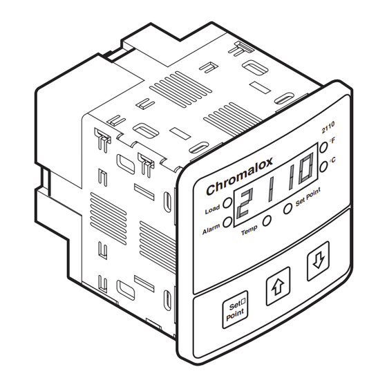
The Chromalox 2110 Temperature controller offers simple setup, flexibility and control features in an attractive, compact design. The 2110 is housed in a rugged, plastic 1/4 DIN package that only requires four inches behind the mounting surface. Straight- forward operation and easy-to-use control features are major strengths of the 2110 controller. -
Page 7: Typical Application
2110 Temperature Controller Typical Application Figure 2.2 shows the 2110 in a typical application. Figure 2.2 Typical Application Model Before installation, please identify your controller model number. The model number appears on a label on the side of the housing. -
Page 8: 3-Installation And Wiring
Section 3—Installation and Wiring Sensor and Control Set the Chromalox 2110 controller’s configuration via mechanical dip switches, located on the bottom of the unit. Factory settings are Type Selection J, TC, °F, and PI Control. Switches are easier to set before mounting. -
Page 9: Removing Mounting Collars
2110 Temperature Controller Mounting Two mounting collars securely hold the 2110 controller in the mounting hole. Remove these mounting collars before installation. Removing Mounting Collars 1. To remove the rear collar, press the sides of the collar. This releases holding tabs on the top and bottom of the collar. -
Page 10: Mounting Dimensions
Mounting Mount the 2110 1. Cut out a 1/4 DIN, 3.6-inch (92mm) square hole in the mount- continued ing panel. 2. Insert the unit into the mounting hole as shown in Figure 3.4. 3. Slide the front mounting collar onto the back of the controller. -
Page 11: Wiring Terminal Identification
Electrical noise can affect the function of any control system. When driving a contactor coil or other inductive load, an appropriate rated AC snubber circuit is recommended (Chromalox Part No. 0149-01305). Connect before power is applied —Make all electrical wiring connec- tions to the back of the controller before power is applied to the unit. -
Page 12: Thermocouple Connections With Shield
Type Material Polarity (+) Polarity (-) iron/constantan white chromel/alumel yellow Make thermocouple wiring connections to terminals as shown in Fig- ure 3.6. TC + TC - Shield Ground Figure 3.6 Thermocouple Connections with Shield Chromalox 2110 Section 3–Installation and Wiring... -
Page 13: Three-Wire Rtd Connections With Shield
2110 Temperature Controller Sensor Input Wiring Three-Wire RTD Inputs IMPORTANT: When making the three-wire RTD input connection, continued make the resistance of all three extension leadwires equal by us- ing the same gauge and same length of wire for optimum accu- racy. -
Page 14: Control Output Wiring-R1 And S0
R1 (1 Amp Relay) and S0 (1 Amp, Solid State Relay) Output Wiring When driving a contactor coil or other inductive load, an appro- priately rated AC snubber circuit is recommended (Chromalox Part. No. 0149-01305), as shown in Figure 3.9. 120/240... -
Page 15: Control Output Wiring-S1 And S2
2110 Temperature Controller Control Output S1 (Solid State Relay, 5 Amps) and S2 (Solid State Relay, 10 Amps) Output Wiring Wiring Note: 2110 model S2 has a fan. 2110 model S1 does not have a fan. continued 120/240 Fuse Neutral Load Figure 3.12... -
Page 16: 4-Adjusting Setpoint And Configuration
2. Apply power to the unit. Set Point 3. To adjust the set point on the Chromalox 2110 Temperature Con- troller, press and hold the Set Point button (see Figure 4.1). The Set Point light is illuminated and the set point value is displayed. -
Page 17: Configuring 2110
2110 Temperature Controller Configuration 4. Press the buttons to adjust the value (only the value is displayed during adjustment). See Figure 4.7. The new value continued is set when the button is released. 5. Press and hold the Set Point ( ) button and press the button to advance to the next menu. - Page 18 A low setting will not allow process temperature to reach to set point quickly enough. A setting of “0” turns off automatic reset. This menu is active only when the dip switch is set to “PI”. Chromalox 2110 Section 4–Adjusting Set Point and Configuration...
- Page 19 2110 Temperature Controller Configuration Menu Adjustable Factory Security Code Function Range Default Level Menus Cycle Time .1 to 60.0 Output CYCL continued The time for the output to Sec. R1, R3 = complete ON to OFF to 30 sec. ON cycle. Used only with S0, S1, proportional control.
-
Page 20: 5-Controller And Alarm Operation
For example, if the cycle time is 1 second and the 2110 needs a 75% output, the output will be on for 3/4 of a second and off 1/4 of a second. Units with relay control outputs (R1 or R3) are shipped with a 30-second cycle time. -
Page 21: 6-Replacing Output Modules
20A Mechanical Relay output cards control small cartridge heater or strip heater loads directly, eliminating the need for a remote contac- tor or solid state relay. If a larger load is required, the 2110 can be configured with a 1A Pilot Duty Relay or Solid State Relay Drive. -
Page 22: Replacing Output Module
The Control Output Modules have a default cycle time of 1 second (fast switching) or 30 seconds (slow switching) (See table on page 17). After replacing a control output, the 2110 verifies at power up if a slow or fast cycle time output has been installed. If an output with a different default cycle time is installed, the 2110 will change the cycle time to the new device’s default. -
Page 23: 7-Calibration
The 2110 always retains the original factory calibration values for the J, K, and RTD inputs. In an application, only one of these sensor inputs will be used. The 2110 only can retain manual calibration for a single sensor. Calibration Notes: continued Section 7–Calibration... - Page 24 5. To access the calibration menu, you need level C (736) security. Sensor Calibration: 1. Set the 2110 selection switch to RTD or TC. If TC is selected, then set the selection switch to J or K. 2. Connect the sensor simulator to the sensor input terminals.
-
Page 25: 8-Specifications
2110 Temperature Controller Section 8—Specifications Control Modes ........ ON/OFF; PI—Proportional with integral Control Adjustments Proportional Band ..... 1 to sensor span maximum Automatic Reset ......0.0 to 100.0 repeats/minute Cycle Time......... 0.1 to 60.0 seconds On/Off Deadband ...... 1° to 100°F or °C Set Point Upper Limit .... -
Page 26: 9-Troubleshooting
Section 9—Troubleshooting The following Troubleshooting Guide offers simple solutions to common problems and explains the 2110’s Error Messages. Re- view this section for a possible solution to your problem before contacting Chromalox. Note: For each symptom, perform correction steps in the order listed. -
Page 27: Troubleshooting
2110 Temperature Controller Troubleshooting Symptom Probable Cause Correction Steps continued Process not in 1. Incorrect settings 1. Check Proportional control Band setting and Auto- 2. Thermocouple matic Reset setting Wiring 2. Check thermocouple polarity Instrument continu- 1. Severe electrical 1. Separate sensor wiring... - Page 28 Limited Warranty: Please refer to the Chromalox limited warranty applicable to this product at http://www.chromalox.com/customer-service/policies/termsofsale.aspx. 1347 HEIL QUAKER BLVD., LAVERGNE, TN 37086 Phone: (615) 793-3900 www.chromalox.com...
Need help?
Do you have a question about the 2110 and is the answer not in the manual?
Questions and answers