Advertisement
Quick Links
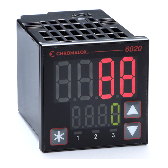
6020 & 8020 Temperature Controller
Quick Start Manual – 0037-75555 (PK529)
This manual is intended to provide only the basic installation and operation instruc-
tions. The 6020 & 8020 Controllers are pre programmed with one of two Default
Settings profiles depending on the controller design (see Section 6). Setpoint tem-
perature may be established in Setup Mode (See Section 7).
Please refer to manual, PK530, for complete installation & operation details. The
most current revision of PK530 may be found on the Chromalox website: www.
chromalox.com
1. IMPORTANT SAFEGUARDS
ELECTRIC SHOCK HAZARD: Read and understand all instructions before
installing, servicing or operating this controller. Failure to do so could
result in equipment or property damage as well as personal injury and
even death.
Installation should be only performed by technically competent person-
nel. It is the responsibility of the installing engineer to ensure that the
configuration is safe. Local regulations regarding electrical installation
& safety must be observed - e.g. US National Electrical Code (NEC) and/
or Canadian Electrical Code. Impairment of protection will occur if the
product is used in a manner not specified by the manufacturer.
HIGH VOLTAGE is used in the operation of this equipment. DEATH ON
CONTACT may result if personnel fail to observe safety precautions.
Learn the areas containing high-voltage connections when installing or
operating this equipment.
Be careful not to contact high-voltage connections when installing or op-
erating this equipment. Before working inside the equipment, turn power
off and ground all points of high voltage potential before touching.
ELECTRIC SHOCK HAZARD. Any installation involving control equip-
ment must be performed by a qualified person and must be effectively
grounded in accordance with the National Electrical Code to eliminate
shock hazard.
2. INSTALLATION
Installation Guidance
• Standards compliance shall not be impaired when fitted into the final installation.
• Designed to offer a minimum of Basic Insulation only.
• Ensure that supplementary insulation suitable for Installation Category II is achieved
when fully installed.
• To avoid possible hazards, accessible conductive parts of the final installation
should be protectively earthed in accordance with EN61010 for Class 1 Equipment.
• Output wiring should be within a Protectively Earthed cabinet.
• Sensor sheaths should be bonded to protective earth or not be accessible.
• Live parts should not be accessible without the use of a tool.
• When fitted to the final installation, an IEC/CSA APPROVED disconnecting device
should be used to disconnect both LINE and NEUTRAL conductors simultaneously.
• Do not to position the equipment so that it is difficult to operate the disconnecting
device.
Panel-Mounting
The mounting panel must be rigid, and may be up to
6.0mm (0.25inch) thick. Cutout sizes are:
1/16: Width = 45mm, Height = 45mm,
1/8: Width = 45mm, Height = 92mm
For n multiple instruments mounted sideby-side, cut-
out width W is 48n-4mm.
Mounting
Panel
Instrument
Housing
Ratchets
Gasket
1
Insert instrument into the panel cut-out.
2
Hold front bezel firmly (without pressing on display area), and fit mounting clamp.
Push clamp forward, using a tool if necessary, until gasket is compressed and
instrument is held firmly in position.
For an effective IP65 seal against dust and moisture, ensure gasket is
well compressed against the panel, with the 4 tongues located in the
same ratchet slot.
3. REAR TERMINAL WIRING
This diagram shows all possible option combinations.
Check the product configuration before wiring.
Check information label on housing for correct operating voltage before
connecting supply to Power Input.
1/8 DIN size
A
B
Not Fitted
6
Power Input: A6 & B6
5
-
A5 & B5 - Output 3: Relay / SSR 3 +
4
-
A4 & B4 - Output 2: Relay / SSR 2 +
3
-
A3 & B3 - Output 1: Relay / SSR 1 +
2
Input:
+
TC (A1 & A2)
-
1
B1
RTD (A1 , A2 & B2)
DC (A1 & A2)
NEVER DIRECTLY CONNECT DEDICATED CONFIGURATION SOCKET TO A USB PORT.
4. FRONT PANEL
Display and Indication
H
W
Tolerance +0.5, -0.0 mm
All versions of the instrument
have the same basic front
panel layout.
Keypad & General Navigation
Menu navigation, parameter editing and keypad use are described below. See the
Full Installation and Operation Manual sections for further information and exceptions.
General keypad usage & parameter editing:
Press p or q keys to navigate between parameters, To edit a parameter, press Q.
The Parameter name (lower display) flashes when the parameter above can be
edited.
Press p or q to change the parameter value (upper display).
NOTE: Edited values stop changing at the parameters limits.
A further press of p or q past the parameter limit "wraps" the value back to the
start (for example: 0, 1, 2... ...98, 99,100 p 0, 1, 2...)
To confirm the change, press Q within 60 seconds, otherwise the change is rejected.
5. MODE AND MENU STRUCTURE
There are 3 main modes (or menus) on the controller – User Mode, Setup
Mode and Advanced Configuration Mode.
• User Mode – the live screen used for normal operation. The process variable
can always be seen in this mode
• Setup Mode – allows access to the most often used parameters
• Advanced Configuration Mode – access all parameters via sub-menus
To navigate to Setup or Advanced Configuration from User Mode:
Press and hold down Q and press p for Setup Mode
Press and hold down Q and press q for Advanced Configuration Mode.
Fuse:
100 – 240V AC – 1A anti-surge
Returning to User Mode from other modes:
24V AC / DC – 315mA anti-surge
After 120 seconds without key activity the unit returns automatically to the 1st
C
User mode screen - Or - Press and hold down Q and press p to move back up
N
~
-
one level.
L
~ +
Advanced Configuration Mode
100 - 240V AC
The Advanced Configuration Menu provides access to all of the features
24V AC
24V DC
available in these controllers. Here you will find the following sub-menus: User
(USEr), Input (InPt), Calibration (CAL), Output (OUtP), Control (COnt), Setpoint
C6
(SPti), Alarm (ALM), Communications (CoM), Display (diSP) and Product
Use Copper Conductors on
all connections except
Information (InFo).
thermocouple input.
Please refer to the Full Installation & Operation Manual for these additional sub-
Single Strand wire gauge
menus and their settings.
max 1.2mm (18SWG).
Mode Access and Lock Codes
Separate lock codes can be set for the Setup Mode and for the Advanced
B (Rx / Tx-)
RS485 (if fitted)
C1 & C2
Configuration Mode (Adu).
A (Rx / Tx+)
S.Loc Setup Mode lock code – default 10.
A.Loc Advanced Configuration Mode lock code – default 20.
Output LED
indicators
Up / Increment
p
Enter / Confirm
q
Down / Decrement
Advertisement

Related Manuals for Chromalox 6020


Summary of Contents for Chromalox 6020
- Page 1 1/8: Width = 45mm, Height = 92mm This manual is intended to provide only the basic installation and operation instruc- tions. The 6020 & 8020 Controllers are pre programmed with one of two Default For n multiple instruments mounted sideby-side, cut- Settings profiles depending on the controller design (see Section 6).
- Page 2 Depth Behind Panel: 67mm with sealing gasket fitted. are available, such as 0-50, 10-50, 0-5, 1-5, 0-10 0037-75555 and 2-10. Please refer to the full Installation and Weight: 0.20kg maximum August 2015 Operation Manual for details. © 2015 Chromalox, Inc.
Need help?
Do you have a question about the 6020 and is the answer not in the manual?
Questions and answers