
Related Manuals for Chromalox 3204


Summary of Contents for Chromalox 3204
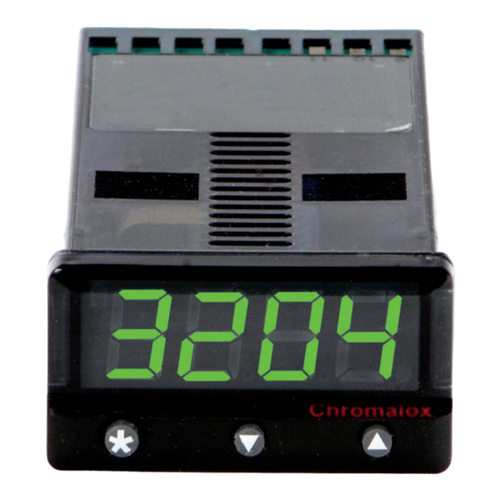
- Page 1 Installation & Operation Manual 3204 1/32 DIN Autotune Temperature Controller PK511-1 0037-75373 January 2017...
-
Page 2: Table Of Contents
Table of Contents Contents Page Number Safety & Warranty ..............................iv Functions Menu ..............................1 Quick Start ................................3 Quick Start Set-Up ............................3 Introduction ................................4 The Controller ..............................4 Overview .................................. 4 Installation ................................4 Set-Up ................................4 Autotune ................................ - Page 3 Contents Page Number Error Messages ..............................14 Recommendations ............................14 Autotune Data in Tech ............................14 Improving Control Accuracy..........................15 Using CHEK Accuracy Monitor ........................15 Function List ................................. 16 Level 1 ................................16 Level 2 ................................17 Level 3 ................................17 Level 4 ................................
- Page 4 Warranty and Returns Statement CHROMALOX MAKES NO WARRANTY OF MER- CHANTABILITY OR FITNESS FOR A PARTICULAR These products are sold by Chromalox under the war- PURPOSE WITH RESPECT TO THE PRODUCTS. ranties set forth in the following paragraphs. Such war-...
- Page 6 Main Setpoint (SP1) Process Temperature (PV) LED Indication or Setpoint (SP) Value Second Setpoint (SP2) LED Indication INSTRUMENT ADJUSTMENTS To enter or exit program mode: Press together for 3 seconds To scroll through functions: Press To change levels or options: Press together or together...
-
Page 7: Quick Start
Quick Start After power-up the controller requires programming Press s once. The display will now alternate with the following information: and nonE • Type of Sensor 2. Select unit. • Operating unit Press and hold H and use the s or t buttons to •... -
Page 8: Introduction
A user’s manual is supplied with the comms option. For more information, contact Chromalox. See contact The 3204 control can be optimized with a single shot information on the last page of this manual. autotune either on initial warm-up or at setpoint. A sec-... -
Page 9: Cycle-Time
Factory Set The TUNE method normally achieves the best results. Starting with the load cool, tuning occurs during warm- To use the 20 sec factory set cycle-time, no action is up preventing overshoot. This method of tuning is rec- needed whether Autotune is used or not. ommended. -
Page 10: Set-Up
Set-Up To Select Sp1 This section gives details on: (Main setpoint output device) • Power-up, • how to select the input sensor, Press and release the s button, the controller will now • how to select the operating unit, alternately display and nonE. -
Page 11: Menu Navigation
Menu Navigation To Change an Option Value or Setting The facilities of the controller are selected from the multilevel menu using the front panel mounted buttons. Press and hold the H button, then press s to increase Each level within the multi-level menu offers different or t to decrease the value or select the next option. -
Page 12: Autotune
Autotune Select the most appropriate method of Au- The controller will alternately display and oFF. totune, Tune or Tune at Setpoint, to suit the Press and hold H and press s once, application. The controller will alternately display and on. Note: The proportional cycle-time can be pre- Exit program mode. -
Page 13: Proportional Cycle-Time
The TUNE AT SETPOINT program will now start. The REMINDER OF INSTRUMENT ADJUSTMENTS controller will alternately display and the pro- cess temperature. • Press s and t together for 3 seconds for pro- gram entry or exit. Note: During tuning, the main setpoint (SP1) LED •... - Page 14 If this cycle-time is suitable press and hold both s and To Pre-Select Cycle-time Before Autotune t buttons for 3 seconds to enter it into the controllers Before selecting Autotune, enter program mode. memory. Select If the calculated cycle-time is not compatible with the Press and hold the H button, then press s to increase or t to decrease the displayed cycle-time.
-
Page 15: Programmer
Programmer Ramp-Soak Deg. Deg. Soak This feature enables the controller to ramp up or down Target setpoint Ramp°/hour from current temperature to a target setpoint at a pre- determined rate. It then controls at the target setpoint Ramp°/hour Target for an adjustable soak period before switching off the setpoint Soak heat output. -
Page 16: Second Setpoint (Sp2)
Second Set-Point (SP2) The second setpoint SP2 can be used to trigger an Select level 1 and select and set the required alarm or as a proportional control output. setpoint value (y°). To Configure SP2 as an Alarm If the factory set hysteresis 2.0°C/3.6°F is unsuitable: Enter program mode. -
Page 17: Sp2 Alarm Condition Table
SP2 Output and LED Indication States - SP2 Alarm Annunciator In Alarm Condition When an SP2 alarm mode is selected in SP2.A the alarm annunciator -AL- is displayed, alternating with Alarm On-Off Proportional the process temperature, during alarm condition. Type Operating Mode Operating Mode Deviation... -
Page 18: Error Messages
Error Messages Sensor Fault Action: 1. Change the conditions. eg. raise setpoint Display flashing: and FaiL 2. Try At.SP 3. Check SP1.P percentage power Indicates: thermocouple burnout RTD/Pt100 (see IMPROVING CONTROL ACCURACY) open or short circuit or negative 4. If the error message persists, call for advice. over-range. -
Page 19: Improving Control Accuracy
Improving Control Accuracy The following functions are to assist engineers with Using the Control accuracy monitor machine development, commissioning and trouble- To start the monitor select shooting. Read Sp1 Output Percentage Power Note: During monitoring either return to normal op- eration or remain in program mode. -
Page 20: Function List
Function List Too short Too long (overshoots and oscillates) (slow warm up and response) The functions and options are available in four levels. 1 - 200 seconds [25] Too short Too long (overshoots and oscillates) (slow warm up and response) Note: A Functions Menu is shown on the cover SP1 Derivate Time/Rate fold-out... -
Page 21: Level 2
[oFF] 0 to 1440 min 0.1 - * °C/°F [2.0 °C/3.6°F] Sets the soak time Adjust SP2 hysteresis or proportional band/gain (see CyC.2 setting) SP2 OPERATING PARAMETERS * 25% sensor f/s 0 to * °C/°F Adjust SP2 setpoint [on.oFF] 0.1–81 seconds * Deviation Alarms DV.hi, DV.Lo, bAnd 25% sensor Select SP2 ON/OFF or Proportional Cycle-Time maximum. - Page 22 Meter, data logger. See ADVANCED SETTINGS. [0.0] to ±25% sensor f/s Select output modes: Direct/Reverse Zero sensor error, see SPAn [oFF] Settings affect fail safe state. Select control accuracy monitor [Var] [1r.2d] Reverse Direct Read control accuracy monitor 1d.2d Direct Direct 1r.2r Reverse...
-
Page 23: Factory Set Output Options
Factory Set Output Options Dual Relay or Dual SSd Output Models Dual Relay Models preallocate SP1 to terminals 3 and 4. The table below details the factory set output options. rLY2 is a 1A electromechanical relay, and SSd1/SSd2 Note: Output device rLY/rLY1 is rated 2A is an identical second SSR drive output. -
Page 24: Calibration To Other Instrument
Make the following manual adjustment: Adjust using the Function In level 1 double the value of 1. Choose a temperature near the bottom and another near the top of the scale. If no improvement, return to the original value and; In 2. - Page 25 Figure 1 3. Allocate the output devices at function described in SET-UP, enter the configuration into 10 11 12 13 14 15 the memory and proceed as follows: – – Calculate the values for the controller settings for 5Vdc 15mA using the example below as a guide: Outputs...
-
Page 26: Communications
Additional Units (Baud rate) The setting determines the serial baud communication data transmission rate in bits/sec, and must match the PC settings. Default = 9600. PC Com Port 3204 3204 3204 DB-9 Pin Options: Rear Terminal Unit 2 Unit 1 1200;... - Page 27 Configuring Instrument Comms Settings This should also be done immediately after power- To Read or Adjust Comms Settings up, and is only possible from the instrument front Baud Rate panel. Press s once display alternates and 9600 baud On power-up the controller will display the self test se- (Default setting) quence followed by Alternating, and none.
-
Page 28: Mechanical Installation
Mechanical Installation MOUNTING 3204’s are sleeve mounted with their front bezel as- sembly rated NEMA4/IP66 provided that: To mount a Controller proceed as follows: • the panel is smooth and the panel cutout is accurate; 1. Check that the controller is correctly orientated and •... -
Page 29: Electrical Installation
Electrical Installation Supply Voltage To avoid possible hazards, accessible conductive parts of the final installation should be protectively earthed in The controllers are designed for use with the following accordance with EN6010 for Class 1 Equipment. supply voltages: Output wiring should be within a protectively earthed 100-240V 50-60 Hz ±10% 4.0VA cabinet. -
Page 30: Specifications
Specifications Thermocouple General 9 types Displays: Main, 4 Digits high bright- Standards: IPTS/68/DIN 43710 ness green LED. 10mm CJC Rejection: 20:1 (0.05°/°C) typical (0.4”) high. External Resistance: 100Ω maximum Digital range -199 to 9999 Hi-res mode -199.9 to Resistance Temperatrue Detector 999.9 RTD-2/Pt100 2 Wire LED output indicators -... -
Page 31: Ordering Information
Ordering Information Model 3204 1/32 DIN Auto Tuning PID Controller 3204 Compact 1/32 DIN AutoTune PID controller with the following standard features: User selectable inputs (thermo- couple, RTD or 0-20, 4-20 mV or mA** linear process inputs), dual outputs for heat, cool and alarm; single ramp &... -
Page 32: Input/Sensor Selection
2* Linearity B: 5° (70º - 500°C) K/N:1° >350°C exceptions: R/S: 5°<300°C T:1° <- -25° >150°C RTD/Pt100: 0.5° <-100°C Limited Warranty: Please refer to the Chromalox limited warranty applicable to this product at http://www.chromalox.com/customer-service/policies/termsofsale.aspx. Chromalox, Inc. 1347 Heil Quaker Boulevard...
Need help?
Do you have a question about the 3204 and is the answer not in the manual?
Questions and answers