
Related Manuals for Chromalox 8003


Summary of Contents for Chromalox 8003
- Page 1 8003 1/8 DIN Temperature Controller ❒ USER’S MANUAL Issue Date April 1994 0037-75212...
-
Page 2: Table Of Contents
Contents Model Identification ... Page ii Dimensions and Panel Cutout ...1 Wiring ...2 Hardware Setup ...3 Configuration Mode ...4 Operator Mode ...9 Error Messages ... 12 Warranty and Return ... 14 Chromalox 8003 User's Manual... -
Page 3: Model Identification
Relay, 2 Amps at 250 Vac (Resistive) or SSR Drive, 14V @ 20mA, Jumper Selectable Code Options None Alarm #2, 2 Amps at 250 Vac (Resistive load) Code Power Supply 100/240 Vac 24 Vac/dc Code Add to complete model number Typical Model Number Chromalox 8003 User's Manual... -
Page 4: Dimensions And Panel Cutout
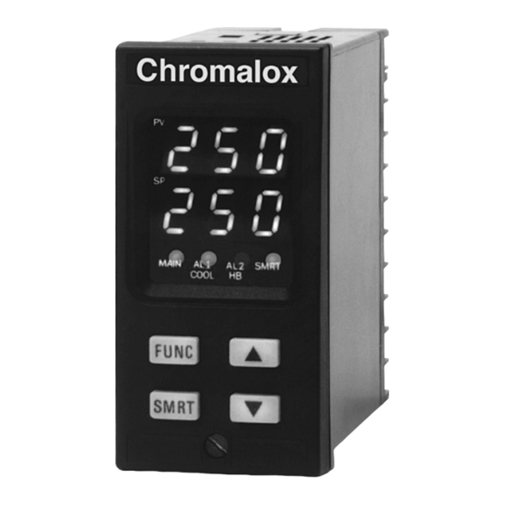
Dimensions in inches (mm in parenthesis) (12.8) (89) Chromalox 8003 User's Manual Chromalox (96) MAIN AL1 AL2 SMRT COOL HB FUNC SMRT (48) 1.77 (45) 3.62 (92) (125) (60) -
Page 5: Wiring
(i.e. for J T/C, use type “J” thermocouple extension wire). • When using shielded sensor cable, ground the shield at one end only. Operating (mF) (Ω) Voltage (mA) 0.047 260 Vac 260 Vac 0.33 260 Vac Chromalox 8003 User's Manual... -
Page 6: Hardware Setup
3. Set J304 and J305 as shown in the following figure. 3 2 1 J305 (MAIN output) 1-2 = SSR 2-3 = Relay 3 2 1 J304 (AL1, Cool.) 1-2 = SSR 2-3 = Relay Chromalox 8003 User's Manual J305 PZ22 PZ21 J304 PZ20 PZ19 PZ18 PZ17 PZ16 PZ15... -
Page 7: General Operation
General Operation There are two setup modes for the 8003: • Configuration Mode • Operator Mode In general, the Configuration Mode is the initial setup of the controller when first installed. Input type and alarm setup are examples of Configuration Mode settings. The... - Page 8 Note: the minimum input span (P3 - P2) is 300°C or 600°F for TC input and 100°C or 200°F for RTD input. Chromalox 8003 User's Manual P4 = Output Configuration H = Heating HC = Heating / cooling...
- Page 9 When P13 is different from 0, P14 is programmable from -20 % to + 20 % of P13 value. -20% to +20% Readout Readout Real curve Adjusted curve Input P13 = 0 Chromalox 8003 User's Manual Real curve Adjusted curve Input...
- Page 10 From 500 to 999 = SP, A1 and A2 parameters may be modified and other Operator Mode parameters may be accessed. Chromalox 8003 User's Manual • When configuration is completed, the instrument shows " -.-.-. " on both displays. End of Configuration •...
- Page 11 SMART function in heating control only—This parameter may be programmed from 1.0% to P27 value. P29 = Proportional Band Minimum Value is Adjustable SMART function in heating/cooling only—This parameter may be programmed from 1.5% to P27 value. Chromalox 8003 User's Manual...
-
Page 12: Smart Function
Notes: 1. When ON/OFF control is programmed (PB = 0), the SMART function is disabled. 2. The SMART enabling/disabling is protected by security code. Chromalox 8003 User's Manual Operator Mode 1. Remove the instrument from its case 2. Set the internal switch V2 in closed position 3. -
Page 13: Output Power Off
To return to normal control, press and hold the ▲ pushbutton and then push the FUNC pushbutton. Press and hold both pushbuttons for more than 3 seconds. The instrument then goes to the NORMAL DISPLAY MODE. Chromalox 8003 User's Manual... - Page 14 Integral time (automatic reset), range 1 minute and 20 seconds to 20 minutes and 00 seconds, or if blank integral is disabled. Chromalox 8003 User's Manual Derivative (rate), range 1 second to 9 minutes and 59 seconds. If 0, derivative is disabled.
-
Page 15: Error Messages
Note: When an overrange condition is detected, the instrument forces the control output to the minimum possible value. When an underrange condition is detected, the instrument forces the control output to the maximum possible value. Chromalox 8003 User's Manual... -
Page 16: Error List
(ex. 209 Err shows an Error on P9 parameter) RTD input calibration error TC input calibration error RJ input calibration error CT input calibration error Chromalox 8003 User's Manual Control parameters error Auto-zero error RJ error General error during calibration procedure Note: 1. -
Page 17: Warranty And Return
AND LIMITATIONS Clause, it is specifically understood that Products and parts not manufactured and work not performed by Chromalox are warranted only to the extent and in the manner that the same are warranted to Chromalox by Chromalox’s vendors, and then only to the... - Page 18 In no event shall buyer be entitled to incidental or consequential damages and buyer should hold Chromalox harmless therefrom. Any action by buyer arising hereunder or relating hereto, whether based on breach of contract, tort...
-
Page 19: Instruments And Controls
Chromalox ® INSTRUMENTS AND CONTROLS 1382 HEIL QUAKER BOULEVARD LAVERGNE, TN 37086-3536 PHONE (615) 793-3900 FAX (615) 793-3563...
Need help?
Do you have a question about the 8003 and is the answer not in the manual?
Questions and answers