Table of Contents
Advertisement
Quick Links
Installation
Instructions
If you have questions, call 800-GE-CARES or visit our website at: www.monogram.com
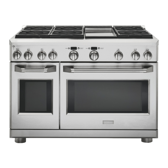
Professional Ranges
48" Natural Gas Models
ZDP48N4G
ZDP48N6R
ZDP48N6D
48" LP Gas Models
ZDP48L4G
ZDP48L6R
ZDP48L6D
36" Natural Gas Models
ZDP36N6
ZDP36N4R
ZDP36N4D
36" LP Gas Models
ZDP36L6
ZDP36L4R
ZDP36L4D
30" Natural Gas Model
ZDP30N4
30" LP Gas Model
ZDP30L4
Advertisement
Table of Contents

Related Manuals for Monogram ZDP30L4


Summary of Contents for Monogram ZDP30L4
-
Page 1: Installation Instructions
Installation Instructions If you have questions, call 800-GE-CARES or visit our website at: www.monogram.com Professional Ranges 48" Natural Gas Models ZDP48N4G ZDP48N6R ZDP48N6D 48" LP Gas Models ZDP48L4G ZDP48L6R ZDP48L6D 36" Natural Gas Models ZDP36N6 ZDP36N4R ZDP36N4D 36" LP Gas Models... -
Page 2: Before You Begin
électrique » à la page 7. the gas range should be installed in accordance with the National Fuel Gas Code ANSI 223.1, latest For Monogram local service in your area, edition and National Electrical Code ANSI/NFPA 70, 1.800.444.1845. latest edition. -
Page 3: Table Of Contents
ZDP30N4 ZDP48L6R – 6 gas burners and grill ZDP48L6D – 6 gas burners and griddle 30" Liquid Propane Gas Model: ZDP30L4 BACKSPLASH ACCESSORIES Backsplash for 30" Models: ZX9B30HSS – 9" high backsplash All models require 12" min. clearance to a vertical ZX22B30HSS –... -
Page 4: Product Dimensions And Clearances
Design Information PRODUCT DIMENSIONS AND CLEARANCES 36" Wide Range Models 48" Wide Range Models 22" 22" 12" 12" 1-1/2" 1-1/2" 35-1/4"-36-3/4" 35-1/4"-36-3/4" 47-7/8" 28-1/4" 28-1/4" 35-7/8" 48" and 36" Range Models 29-1/16" 12" Min. to Combustibles or 9-1/2" 0" Min. to Combustibles 3/4"... -
Page 5: Product Dimensions And Clearances
Design Information PRODUCT DIMENSIONS AND CLEARANCES 30" Wide Range Models 27-3/8" 9-1/2" 22" 3/4" 22" High 9" 36" Min. Backsplash 22" to Combustibles with Shelf 1-1/2" 9" 9" High Backsplash 35-1/4"-36-3/4" 0" Clearance 26-3/4" 29-7/8" 26-3/4" 29-1/4" 43-7/8" NOTE: Refer to Vent Hood 30"... -
Page 6: Advance Planning
Design Information ADVANCE PLANNING TOOLS REQUIRED Refer to “Dimensions and Clearances” for appropriate • Saw placement and necessary clearances when planning • Measuring tape the installation. • Carpenter’s square • Cabinetry can not be installed directly above the • Pipe wrench range. -
Page 7: Installation Preparation
Installation Preparation POWER SUPPLY LOCATIONS If the electrical service provided does not meet the above specifications, it is recommended that a Gas Supply: licensed electrician install an approved outlet. • The natural gas models are designed to operate at 5" •... -
Page 8: Step 1 Remove Packaging
Installation STEP 1 REMOVE PACKAGING Slot Before moving the range indoors: • Remove outer carton and packing material from the shipping base. Hinge lock Pull the hinge locks down to unlock. Remove oven doors: • Fully open the door. • Each hinge has a hinge lock. Close the hinge latch down against the door frame. -
Page 9: Step 2 Level The Range
Installation STEP 2 LEVEL THE RANGE NOTE: Rear range leveling legs are not accessible after • Adjust the height of the range to countertop height installation. or higher. • Check to be sure the adjoining cabinets/countertops IMPORTANT: The range should always be installed are level, front to back and left to right across the at countertop height or higher. -
Page 10: Step 3, Install Anti-Tip Device
Installation STEP 3 INSTALL ANTI-TIP DEVICE (CONTINUED) (2) Wood Screws into Small Hole For Wood Back Wall Installations (2 Total) (All Installations) (2) Large Holes For Concrete Installations Back Small Holes For Wood Wall Installations (2 Total) Wood Slide Strip Dimension A 1/2"... -
Page 11: Step 4 Connect Range To Gas
Installation STEP 4 CONNECT RANGE TO GAS Assure that gas supply is turned off at the shut-off CAUTION: valve: Do not use a flame to check for gas leaks. • Connect flexible metal connector to incoming gas line pipe stub located on the left side on the bottom back MISE EN GARDE : of the range. -
Page 12: Step 5 Connect Electrical
Installation STEP 5 CONNECT ELECTRICAL STEP 7 REPLACE OVEN DOOR(S) Plug power cord into properly grounded receptacle. IMPORTANT: Do not lift the door by the handle. To replace the oven doors: • Firmly grasp the door at the top sides. This is critical. STEP 6 SLIDE RANGE INTO •... -
Page 13: Step 8 Assemble And Adjust Burners
Installation STEP 8 ASSEMBLE AND ADJUST BURNERS Assemble burners as shown. Check to be sure that burner heads and caps are securely seated. Pin(s) must Burner Cap completely engage holes to ensure proper assembly. Burner Head • Check for proper ignition: (Brass) –... -
Page 14: Finalize Installation
Installation FINALIZE INSTALLATION Place the burner grates over the burners. Press corner The griddle has two leveling screws beneath the rear of the grate to the cooktop. The grates should be seated flue cover that can be used to adjust to the desired slope. and should not rock. -
Page 15: Install Backsplash Accessory
Installation INSTALL 9” or 12” HIGH BACKSPLASH Slots for Vertical Adjustment • Install and level the range or cooktop according to the Back section installation instructions. • Remove the backsplash packaging. Select the back, wall mount panel with mounting screw slots. 1/8"... - Page 16 NOTE: While performing installations described in this book, safety glasses or goggles should be worn. For Monogram ® local service in your area, call 1.800.444.1845. NOTE: Product improvement is a continuing endeavor at General Electric. Therefore, materials, appearance and specifications are subject to change without notice.
Need help?
Do you have a question about the ZDP30L4 and is the answer not in the manual?
Questions and answers