Advertisement
Quick Links
For more detailed installation, configuration, programming, and operating
instructions, refer to the NXP-TPI/4 Touch Panel Interface Instruction Manual
available on-line at www.amx.com.
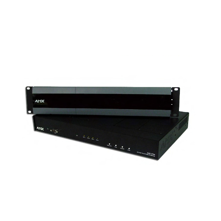
Main unit
FIG. 1
NXP-TPI/4 NetLinx Touch Panel Interface 4 (showing main unit and TP4 cards)
ATTENTION!
Verify you are using the latest NetLinx Master and NXP-TPI4 firmware
(available from www.amx.com). Verify the TPDesign4 program being used is
Version 2.6 or higher.
Overview
The NXP-TPI/4 (FIG. 1) is a touch panel interface that supports AMX's 4th
generation graphics (G4) consisting of both rich colors and support for
high-contrast images. This G4 interface device is capable of mixing
Video/RGB inputs and then combining those inputs with graphics, which can
then be displayed on a variety of monitors.
Specifications
NXP-TPI/4 Specifications
Dimensions:
NXP-TPI/4
• 2.12" x 16.95" x 10.24" (5.38 cm x 43.05 cm x 26.01 cm)
(FG2275-01)
• 1.05" x 2.80" x 8.60" (VID with connector - 9.34")
TP4-RBG/VID
(2.67 cm x 7.11 cm x 21.84 cm (VID with connector - 23.72 cm))
(FG2275-20/10)
Power:
NXP-TPI/4
• 750 mA @ 12 VDC (using a 2-pin PSN power supply)
• ~ 400 mA @ 12 VDC power consumption (per card)
Input Cards
(configuration dependant)
Memory:
• 64 MB SDRAM (upgradable to 256 MB)
• 64 MB Compact Flash (upgradable to 1 GB) - factory
programmed
• Refer to the NXP-TPI/4 Instruction Manual for upgrade
information.
Front
• SERIAL programming port
• LED Indicators - PWR, ICSP (ICSNet communication), and 4
Components:
yellow LEDs (for each input card)
• Pushbuttons - RESOLUTION, TOUCH, CALIBRATE, and
SETUP
Rear
• Touch Input connector communicates with the touch panel
• 2 PS/2 ports and 2 USB ports (both for keyboard and mouse
Connectors:
control)
• VGA Output connector sends out a max. resolution of 1280 x
1024
• 1 RJ-45 Ethernet port and 2 RJ-45 ICSNet ports for network
control
• Audio connector for use with a 3.5 mm mini-jack
Slots:
• 4 available input card slots.
• Use any combination of TP4-RGB and TP4-VID input cards
Output
• 640x 480 @60 Hz to 1280 x 1024 @ 60 Hz
Resolution:
Input Resolution: • 640x 480 @60 Hz to 1600 x 1200 @ 60 Hz
Included
• 2-pin PWR connector (41-5025)
• Assembly Kit (Four-#10-32 screws and Four-#10 washers)
Accessories:
(KA0001)
• NXP-TPI/4 Faceplate (MA2001-11)
• NXP-TPI/4 Quick Start Guide (93-2275)
• Rack Ear brackets (Left/Right) for shelf, wall, and under-table
mounting (62-2275-07)
NXP-TPI/4
Removing the Input Card Covers
1.
2.
3.
4.
Installing Input Cards
1.
2.
TP4 cards
3.
4.
TP4-VID
Grounding Bolt
FIG. 2
5.
6.
7.
8.
Setting up the TPI/4 for Communication
Step 1: Wiring the NXP-TPI/4
1.
2.
3.
4.
5.
Quick Start Guide
NetLinx Touch Panel Interface 4
Discharge the static electricity from your body by touching a grounded
metal object and disconnect all connectors from the NXP-TPI/4.
Carefully unscrew (counter-clockwise) the two flat phillips-head (top of
each cover) and round Phillips-head screws (rear of each cover) to remove
each card.
Remove the screws from the input cards and repeat this removal process
for each card.
Once the screws are removed, pull the cards upwards and away from the
main TPI/4 unit.
Follow the instructions above for the process used in removing the input
card covers.
Carefully remove the input cards from their static-free bag and note the
location of the accompanying four Phillips-head screws (used in securing
the card to the housing).
Carefully align the male (on the card) and female (on the TPI/4 circuit
board) connectors.
Carefully connect the input card by inserting the male card connectors
vertically down onto the female input connectors on the motherboard, as
shown in FIG. 2.
Input card
connectors (male)
TP4-RGB
Installing Input Cards
Gently push down on the input card (on the location above the pins) until it
is securely connected to the motherboard and fits into a card location.
Once secure, align the input card into the provided "slot" and verify that the
pre-drilled TPD4 card holes (2 on top and 2 at the rear) align with those
located on the rear of the TPI/4.
Repeat steps 1 through 4 to insert other input cards, if necessary.
Screw-in (clockwise) the four screws (per card) to the top and rear of the
unit (along the ends of the inserted input card) to secure each card firmly to
the TPI/4. The flat Phillips-head screws must be used on top and the
rounded Phillips-head screws must be used on the rear of the unit. All
screws must be flush against housing.
Discharge any acquired static electricity by touching a grounded metal
object or by touching the rear grounded bolt.
Attach an earth-ground wire (typically from the equipment rack) to the
grounding bolt, located above the PWR connector on the rear of the TPI/4.
Disconnect any incoming power connector from the rear of the TPI/4.
- A PSN supplies power to the TPI/4 through a 3.5 mm mini 2-pin Phoenix
connector. The incoming PWR and GND cable from a PSN power
supply must be connected to the corresponding location on the rear TPI/4
mini 2-pin PWR connector.
Connect a DB9 touch input cable from the touch panel to the DB9 TOUCH
INPUT connector on the rear of the TPI/4 unit.
Connect the touch panels' HD-15 monitor video cable to the 15-pin VGA
OUTPUT port on the rear of the TPI/4. When using a CRT monitor, use
the NullTouch driver.
Motherboard
card connectors
(female)
Input card covers
Advertisement

Related Manuals for AMX NetLinx Touch Panel Interface 4 NXP-TPI/4


Summary of Contents for AMX NetLinx Touch Panel Interface 4 NXP-TPI/4
-
Page 1: Specifications
(available from www.amx.com). Verify the TPDesign4 program being used is Version 2.6 or higher. Overview The NXP-TPI/4 (FIG. 1) is a touch panel interface that supports AMX’s 4th generation graphics (G4) consisting of both rich colors and support for high-contrast images. This G4 interface device is capable of mixing Video/RGB inputs and then combining those inputs with graphics, which can then be displayed on a variety of monitors. - Page 2 ©2006 AMX. All rights reserved. AMX and the AMX logo are registered trademarks of AMX. AMX reserves the right to alter specifications without notice at any time. 3000 RESEARCH DRIVE, RICHARDSON, TX 75082 • 800.222.0193 • fax 469.624.7153 • technical support 800.932.6993 • www.amx.com FIG. 4...