
Subscribe to Our Youtube Channel
Related Manuals for Samlexpower PST-100S-12A


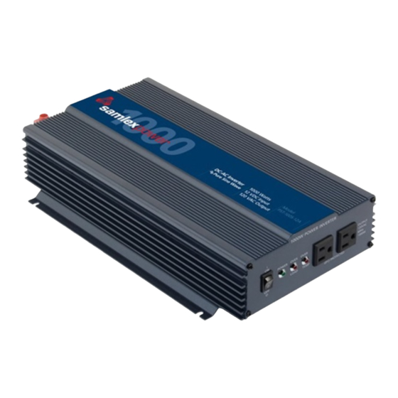
Summary of Contents for Samlexpower PST-100S-12A
- Page 1 1000 Watt Owner's Please read this manual before Manual Pure Sine Wave operating your DC-AC inverter. DC-AC Inverter PST-100S-12A PST-100S-24A...
-
Page 2: Table Of Contents
INDEX Safety Instructions ..................... 2,3 Inverters - General Information ..............4,5,6 Characteristics of Sinusoidal AC Power ............... 7 Advantages of Sine Wave Inverters ..............8 AC Power Distribution and Grounding ............ 9,10,11 Limiting Electromagnetic Interference (EMI) ........... 11 Powering direct/embedded SMPS ..............12 Principle of Operation .................. -
Page 3: Safety Instructions
SAFETY INSTRUCTIONS Please read these instructions before installing or operating the inverter to prevent personal injury or damage to the inverter. GENERAL Installation and wiring compliance • Installation and wiring must comply with the local and national electrical codes and must be done by a certified electrician. Preventing electrical shock • Always connect the grounding connection on the inverter to the appropriate grounding system... - Page 4 Please observe the following precautions: • Ensure that the maximum charging voltage of the battery charger / alternator / solar charge controller is below 16.5 VDC for PST-100S-12A or 33 VDC for PST- 100S-24A • Do not use unregulated solar panels to charge a battery. Under cold ambient temperatures, the output of the solar panel may exceed 18 VDC for 12 V system or 36 VDC for 24 V system.
-
Page 5: Inverters - General Information
INVERTERS - GENERAL INFORMATION Why an inverter is needed The utility grid supplies you with alternating current (AC) electricity. AC is the standard form of electricity for anything that “plugs in” to the utility power. Direct current (DC) electricity flows in a single direction. Batteries provide DC electricity. AC alternates its direction many times per second. - Page 6 Loads that require “surge power” to start Resistive types of loads (like incandescent lamps, toaster, coffee maker, electric range, iron etc) do not require extra power to start. Their starting power is the same as their running power. Some loads like induction motors and high inertia motor driven devices will initially require a very large starting or “surge”...
- Page 7 Power rating of Microwaves The power rating of the microwave generally refers to the cooking power. The electrical power consumed by the microwave will be approximately 2 times the cooking power. The “surge power” of the inverter should be 2 times the electrical power (i.e., 4 times the cooking power).
-
Page 8: Characteristics Of Sinusoidal Ac Power
CHARACTERISTICS OF SINUSOIDAL AC POWER Voltage, current, power factor, types of loads The voltage waveform of 120 VAC, 60 Hz mains / utility power is like a sine wave. In a voltage with a sine wave-form, the instantaneous value and polarity of the voltage varies with respect to time and the wave-form is like a sine wave. -
Page 9: Advantages Of Sine Wave Inverters
ADVANTAGES OF A PURE SINE-WAVE INVERTER OVER A MODIFIED SINE-WAVE INVERTER The output voltage of a sine-wave inverter has a sine wave-form like the sine wave- form of the mains / utility voltage. In a sine wave, the voltage rises and falls smoothly with a smoothly changing phase angle and also changes its polarity instantly when it crosses 0 Volts. -
Page 10: Ac Power Distribution And Grounding
AC POWER DISTRIBUTION AND GROUNDING CAUTION! PLEASE NOTE THAT THE DC INPUT CONNECTIONS ON THIS INVERTER ARE NOT CONNECTED (BONDED) TO THE METAL CHASSIS OF THE INVERTER. BOTH THE INPUT AND OUTPUT CONNECTIONS ARE ISOLATED FROM EACH OTHER. SYSTEM GROUNDING, AS REQUIRED BY NATIONAL / LOCAL ELECTRICAL CODES / STANDARDS, IS THE RESPONSIBILITY OF THE USER / SYSTEM INSTALLER. - Page 11 Grounded Electrical Power Distribution System The National Electrical Code (NEC) requires the use of a “grounded electrical distribution system”. As per this system, one of the two current-carrying conductors is required to be grounded. This grounded conductor is called the “Neutral / Cold / Return”.
-
Page 12: Limiting Electromagnetic Interference (Emi)
Grounding to earth or to other designated ground For safety, the metal chassis of the inverter is required to be grounded to the earth ground or to the other designated ground (For example, in a mobile RV, the metal frame of the RV is normally designated as the negative DC ground). -
Page 13: Powering Direct/Embedded Smps
POWERING DIRECT / EMBEDDED SWITCHED MODE POWER SUPPLY (SMPS) Non-linear nature of current drawn by Switched Mode Power Supplies Power supplies are used to convert AC voltages like 120 VAC to various DC voltages like 3.3 V, 5 V, 12 V, 24 V, 48 V etc. Majority of modern day electronic devices use embedded general purpose Switch Mode type of Power Supplies (SMPS) to drive the electronic circuitry. -
Page 14: Principle Of Operation
PRINCIPLE OF OPERATION The inverter converts the rated DC voltage of the battery to 120 V, 60 Hz. AC voltage. The voltage conversion takes place in two stages. In the first stage, the rated DC voltage of the battery is converted to a high voltage DC using high frequency switching and Pulse Width Modulation (PWM) technique. -
Page 15: Specifying Batteries, Chargers And Alternators
SPECIFYING BATTERIES, CHARGERS & ALTERNATORS The inverter will require Deep Cycle Lead Acid Batteries of appropriate capacity. Lead-acid batteries can be categorized by the type of application: automotive service - Starting/Lighting/Ignition (SLI, a.k.a. cranking) and deep cycle service SLI Batteries Everybody is familiar with the SLI batteries that are used for automotive starting and powering vehicular accessories. - Page 16 Typical battery sizes Below is a chart of some battery sizes applicable for powering inverters: BCI * Group Battery Voltage, V Battery AH 27 / 31 GC2** * Battery Council International ** Golf Cart Reduction in usable capacity at higher discharge rates As stated above, the rated capacity of the battery in AH is applicable at a discharge rate of 20 Hours.
- Page 17 Depth of discharge and battery life The more deeply a battery is discharged on each cycle, the shorter the battery life. Using more batteries than the minimum required will result in longer life for the battery bank. A typical cycle life chart is given at Table 2 below: TABLE 2.
- Page 18 Power in Watts (W) = Voltage in Volts (V) x Current in Amperes (A) Formula 2 For an inverter running from a 12 V battery system (PST-100S-12A), the DC current required from the 12 V batteries is the AC power delivered by the inverter to the load in Watts (W) divided by 10 &...
- Page 19 Charging Batteries The batteries can be charged by using good quality AC powered battery charger or from alternative energy sources like solar panels, wind or hydro systems. Make sure an appropriate battery charge controller is used. It is recommended that the batteries may be charged at 10% to 13 % of the Ampere Hour capacity (20 hour discharge rate).
-
Page 20: Installation
INSTALLATION GENERAL Installation and wiring compliance • Installation and wiring must comply with the local and the national electrical codes and must be done by a certified electrician • In building / residential applications, electrical codes do not allow permanent connection of AC distribution wiring to the inverter’s AC output receptacles. - Page 21 Please observe the following precautions: • Ensure that the maximum charging voltage of the battery charger / alternator / solar charge controller is below 16.5 VDC for PST-100S-12A or 33 VDC for PST- 100S-24A • Do not use unregulated solar panels to charge a battery. Under cold ambient temperatures, the output of the solar panel may exceed 18 V for 12V system or 36 V for 24V system.
- Page 22 (one positive and one negative)cables are used for the connection). Distance up to 4' Distance up to 6’ Ampere rating of battery fuse PST-100S-12A AWG # 2 AWG # 1/0 200A PST-100S-24A AWG # 8...
- Page 23 Reducing RF interference To reduce the effect of radiated interference, twist the DC side cables. To further reduce RF interference, shield the cables with sheathing /copper foil / braiding. Taping battery cables together to reduce inductance Do not keep the battery cables far apart. In case it is not convenient to twist the cables, keep them taped together to reduce their inductance.
- Page 24 AC output connections The inverter uses (2) NEMA 5-15R receptacles for connecting the AC output to devices and appliances fitted with a NEMA 5-15P plug. In these NEMA 5-15 R receptacles, two rectangular slots are connected to the current-carrying conductors of the AC power source inside the inverter.
-
Page 25: Operation
OPERATION Powering on the loads After the inverter is switched on, it takes a finite time for it to become ready to deliver full power. Hence, always switch on the load(s) after a few seconds of switching on the inverter. Avoid switching on the inverter with the load already switched on. This may prematurely trigger the overload protection. -
Page 26: Protection Against Abnormal Conditions
AC output voltage will continue to be available. This warning buzzer alarm indicates that the battery is running low and that the inverter will be shut down after sometime if the voltage at the inverter terminals further drops to 10 V for PST-100S-12A or 20 V for PST-100S-24A. - Page 27 PST-100S-24A, the inverter will be shut down temporarily. The green LED (3) will be switched off and there will be no AC output. The unit will be reset automatically when the voltage drops down to 16.7 V +/- 0.2 V for PST-100S-12A or 33.5 +/-0.2 V for PST-100S-24A.
-
Page 28: Troubleshooting Guide
Buzzer alarm is sounded when DC input voltage is less than charged. Recharge, if low. load is switched on. Voltage 10.7 V for PST-100S-12A or less at DC input terminals reads than 21.4 V for PST-100S-24A 2. Check that the battery cables between 10 to 10.7 V for PST-... - Page 29 SYMPTOM POSSIBLE CAUSE REMEDY The AC output shuts Permanent shut-down of the 1. Reduce the load. down completely. The red AC output due to continuous 2. The load is not suitable as overload LED is lighted. overload beyond the it requires higher power to The green LED is off.
-
Page 30: Specifications
SPECIFICATIONS PST-100S-12A PST-100S-24A Input Voltage..........10.7 to 16.5 VDC ....21.4 to 33 V DC Input Current at No Load ..........< 0.8 A .........< 0.6 A Output Voltage ..........120 V AC +/- 3% ....120 V AC +/- 3% Output Frequency ............60 Hz ........60 Hz Output Voltage Waveform ........Sine Wave......Sine Wave... -
Page 31: Warranty
2 YEAR Limited Warranty The PST-100S-12A/PST-100S-24A manufactured by Samlex America, Inc. (the "Warrantor") is warranted to be free from defects in workmanship and materials under normal use and service. This warranty is in effect for 2 years from the date of purchase by the user (the "Purchaser") - Page 32 110-17 Fawcett Rd T: 604 525 3836 e-mail: samlex@samlexpower.com Coquitlam, B.C. F: 604 525 5221 website: www.samlexpower.com Canada Toll Free: 1 800 561 5885 V3K 6V2 034-2009-010_PST-100-12A_PST-100-24A_Jan2010...
Need help?
Do you have a question about the PST-100S-12A and is the answer not in the manual?
Questions and answers