
Related Manuals for Samlexpower PST-600-48


Summary of Contents for Samlexpower PST-600-48
- Page 1 DC-AC Power Owner's Please read this manual BEFORE Manual Inverter installing your Pure Sine Wave inverter PST-600-48 PST-1500-48...
-
Page 2: Table Of Contents
OWNER'S MANUAL | Index SECTION 1 Safety Instructions ........3 SECTION 2 General Information ........6 SECTION 3 Limiting Electromagnetic Interference (EMI) ....... 13 SECTION 4 Powering Direct / Embedded Switch Mode Power Supplies (SMPS) ............14 SECTION 5 Principle of Operation ....... 16 SECTION 6 Layout ............ -
Page 3: Safety Instructions
1.1 IMPORTANT SAFETY INSTRUCTIONS AND SYMBOLS SAVE THESE INSTRUCTIONS. This manual contains important instructions for models PST-600-48 and PST-1500-48 that shall be followed during installation, operation and maintenance. The following safety symbols will be used in this manual to highlight safety... - Page 4 SECTION 1 | Safety Instructions Installation environment • The inverter should be installed indoor only in a well ventilated, cool, dry environment. • Do not expose to moisture, rain, snow or liquids of any type. • To reduce the risk of overheating and fire, do not obstruct the suction and discharge openings of the cooling fan.
- Page 5 SECTION 1 | Safety Instructions CAUTION! To prevent possibility of paralleling and severe damage to the unit, never use a simple jumper cable with a male plug on both ends to connect the AC output of the unit to a handy wall receptacle in the home / RV. Preventing DC Input Over Voltage It is to be ensured that the DC input voltage of these units is less than 64.0 VDC to pre- vent permanent damage to the unit.
-
Page 6: General Information
SECTION 2 | General Information 2.1. DEFINITIONS The following definitions are used in this manual for explaining various electrical concepts, specifications and operations: Peak Value: It is the maximum value of electrical parameter like voltage / current. RMS (Root Mean Square) Value: It is a statistical average value of a quantity that varies in value with respect to time. - Page 7 SECTION 2 | General Information reactance X to cause the current to lag the voltage by 90° and that of the capacitive reactance X to cause the current to lead the voltage by 90° are exactly opposite and the net effect is a tendency to cancel each other. Hence, in a circuit containing both inductances and capacitances, the net Reactance (X) will be equal to the difference between the values of the inductive and capacitive reactances.
- Page 8 SECTION 2 | General Information Amperes” (LRA) due to low DC resistance of the windings. For example, in motor driven loads like Air-conditioning and Refrigeration Compressors and in Well Pumps (using Pressure Tank), the Starting Surge Current / LRA may be as high as 10 times its rated Full Load Amps (FLA) / Maximum Continuous Running Power Rating.
- Page 9 SECTION 2 | General Information Resistive Load: A device or appliance that consists of pure resistance (like filament lamps, cook tops, toaster, coffee maker etc.) and draws only Active Power (Watts) from the inverter. The inverter can be sized based on the Active Power rating (Watts) of resistive type of loads without creating overload (except for resistive type of loads with Tungsten based heating element like in Incandescent Light Bulbs, Quartz Halogen Lights and Quartz Halogen Infrared Heaters.
- Page 10 SECTION 2 | General Information it sits at zero V for some time before changing its polarity. Thus, any device that uses a control circuitry that senses the phase (for voltage / speed control) or instantaneous zero voltage crossing (for timing control) will not work properly from a voltage that has a Modified Sine Waveform.
- Page 11 SECTION 2 | General Information • Devices that use radio frequency signals carried by the AC distribution wiring. • Some new furnaces with microprocessor control / Oil burner primary controls. • High intensity discharge (HID) lamps like Metal Halide Lamps. These may get dam- aged.
- Page 12 SECTION 2 | General Information Inverter TABLE 2.1: INVERTER SIZING FACTOR Sizing Factor Type of Device or Appliance (See note 1) Air Conditioner / Refrigerator / Freezer (Compressor based) Air Compressor Sump Pump / Well Pump / Submersible Pump Dishwasher / Clothes Washer Microwave (where rated output power is the cooking power) Furnace Fan Industrial Motor...
-
Page 13: Limiting Electromagnetic Interference (Emi)
SECTION 3 | Limiting Electro-Magnetic Interference (EMI) 3.1 EMI AND FCC COMPLIANCE These inverters contain internal switching devices that generate conducted and radi- ated electromagnetic interference (EMI). The EMI is unintentional and cannot be entirely eliminated. The magnitude of EMI is, however, limited by circuit design to acceptable levels as per limits laid down in North American FCC Standard –... -
Page 14: Powering Direct / Embedded Switch Mode Power Supplies (Smps)
SECTION 4 | Powering Direct / Embedded Switch Mode Power Supplies (SMPS) 4.1 CHARACTERISTICS OF SWITCHED MODE POWER SUPPLIES (SMPS) Switch Mode Power Supplies (SMPS) are extensively used to convert the incoming AC power into various voltages like 3.3V, 5V, 12V, 24V etc. that are used to power vari- ous devices and circuits used in electronic equipment like battery chargers, computers, audio and video devices, radios etc. - Page 15 SECTION 4 | Powering Direct / Embedded Switch Mode Power Supplies (SMPS) NOTE: Voltage and current scales are di erent Input voltage Peak inrush current Rated steady state input RMS current Inrush current Fig 4.1: Inrush current in an SMPS NOTE: Voltage Peak Current and current scales...
-
Page 16: Principle Of Operation
SECTION 5 | Principle of Operation 5.1 GENERAL These inverters convert DC battery voltage to AC voltage with an RMS (Root Mean Square) value of 120 VAC, 60 Hz RMS. 5.2 PURE SINE WAVE OUTPUT WAVEFORM The waveform of the AC voltage is a pure Sine Waveform that is same as the waveform of Grid / Utility power (Supplementary information on pure Sine Waveform and its advantages are discussed in Sections 2.2 to 2.4). -
Page 17: Layout
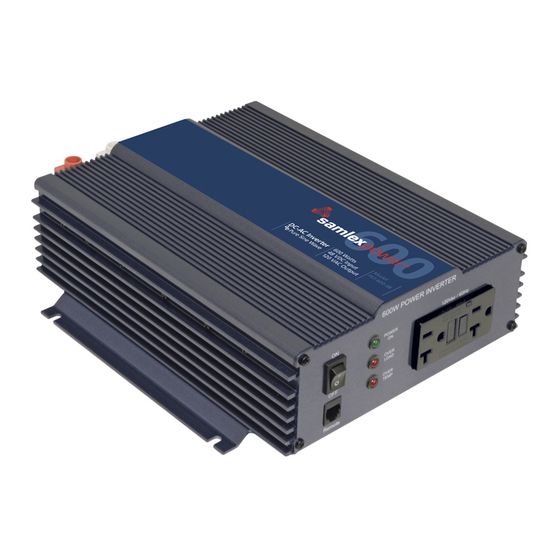
SECTION 6 | Layout PST-1500-48: FRONT PST-1500-48: FRONT - showing compartment containing AC output terminals for hardwiring. PST-1500-48: BACK LEGEND Modular Jack for RC-200 Power ON/OFF Switch Remote Control Green LED - “POWER” Metal Strain Relief Clamp for Red LED - “OVERLOAD” AC Output Cable Red LED - “OVER TEMP”... - Page 18 Hole size: 11 mm / 0.433” with M-8 set screw Positive (+) DC Input Terminal Modular Jack for RC-15A Remote Control Air-suction openings for the fan (At the bottom of the unit − not shown) Fig. 6.2: Layout of PST-600-48 18 | SAMLEX AMERICA INC.
-
Page 19: General Information On Batteries For Powering Inverters
SECTION 7 | General Information on Lead Acid Batteries 7.1 GENERAL INFO For complete background information on Lead Acid Batteries and charging process, please visit www.samlexamerica.com > support > white papers > White Paper - Batteries, Chargers and Alternators. Lead-acid batteries can be categorized by the type of application: Automotive service - Starting/Lighting/Ignition (SLI, a.k.a. - Page 20 SECTION 7 | General Information on Lead Acid Batteries Reserve capacity is the time in minutes for which the battery can deliver 25 Amperes at 80ºF (26.7ºC) till the voltage drops to 1.75V / Cell i.e. 10.5V for 12V battery, 21V for 24V battery and 42V for 48V battery.
- Page 21 SECTION 7 | General Information on Lead Acid Batteries TABLE 7.2: DISCHARGE CURRENT RATES - “C-RATES” (continued from Previous page) "C-Rate" Discharge Current in Amps = Example of C-Rate Hours of discharge time “T” till ÷ Capacity "C" in Ah Discharge Time Discharge Currents the “End Point Voltage”...
- Page 22 SECTION 7 | General Information on Lead Acid Batteries 7.8 REDUCTION IN USABLE CAPACITY AT HIGHER DISCHARGE RATES – TYPICAL IN INVERTER APPLICATION As stated above, the rated capacity of the battery in Ah is normally applicable at a dis- charge rate of 20 Hours.
- Page 23 SECTION 7 | General Information on Lead Acid Batteries TABLE 7.4: STATE OF CHARGE VERSUS STANDING VOLTAGE Standing Standing Standing Standing Percentage of Voltage of Voltage of Voltage of Voltage of Full Charge Individual Cells 12V Battery 24V Battery 48V Battery 100% 2.105V 12.63V...
- Page 24 SECTION 7 | General Information on Lead Acid Batteries The discharge curves in Fig. 7.1 show the % State of Charge versus the terminal voltage of typical battery under different charge /discharge currents, i.e. “C-Rates” and fixed temperature of 80°F. NOTE: The X-Axis of Curves shown in Fig 7.1 indicates the % State of Charge.
- Page 25 SECTION 7 | General Information on Lead Acid Batteries Inverters are normally provided with a protection to shut down the output of the inverter if the DC voltage at the input terminals of the inverter drops below a threshold of around (i) 10V for a 12V battery, (ii) 20V for 24 battery and (iii) 40V for 48V battery.
- Page 26 SECTION 7 | General Information on Lead Acid Batteries 7.15 SERIES AND PARALLEL CONNECTION OF BATTERIES 7.15.1 Series Connection Cable “A” Battery 4 Battery 3 Battery 2 Battery 1 48V Inverter 12V, 12V, 12V, 12V, or 48V Charger 200 Ah 200 Ah 200 Ah 200 Ah...
- Page 27 SECTION 7 | General Information on Lead Acid Batteries Positive connection becomes the Positive terminal of the 48V bank. Similarly, the four Negative terminals of Battery Banks 1 to 4 are paralleled (connected together) and this common Negative connection becomes the Negative terminal of the 48V battery bank. 7.15.3 Series –...
- Page 28 SECTION 7 | General Information on Lead Acid Batteries - All the individual batteries will charge / discharge at the same charging current and thus, will be charged to the same state at the same time. - None of the batteries will see an overcharge condition. 7.16 SIZING THE INVERTER BATTERY BANK One of the most frequently asked questions is, "how long will the batteries last?"...
-
Page 29: Installation
SECTION 7 | General Information on Lead Acid Batteries 125 Ah ÷ 0.8 = 156.25 Ah (note that the actual energy required by the load was 75 Ah). It will be seen from the above that the final rated capacity of the batteries is almost 2 times the energy required by the load in Ah. - Page 30 Ventilation in PST-600-48: It is cooled by convection and by forced air-cooling by temperature controlled fan (behind openings 6, Fig 6.2). The fan draws cool air from air- suction openings on the bottom (11, Fig 6.2) and discharges hot air through the exhaust...
- Page 31 SECTION 8 | Installation 8.2. OVERALL DIMENSIONS 8.2.1 PST-1500-48 The overall dimensions and the location of the mounting slots for PST-1500-48 are shown at Fig. 8.1. 19.2 107.5 468.2 107.5 NOTE: Dimensions are in mm. Fig. 8.1: PST-1500-48 Overall Dimensions & Mounting Slots Fig.
- Page 32 SECTION 8 | Installation 8.2.2 PST-600-48 The overall dimensions and the location of the mounting slots for PST-600-48 are shown in Fig. 8.2. 15.2 15.2 276.2 NOTE: Dimensions are in mm. NEG – NEG – POS + WARNING: Reverse polarity will damage the unit.
- Page 33 SECTION 8 | Installation 8.3 MOUNTING ORIENTATION The unit has air intake and exhaust openings for the cooling fan. It has to be mounted in such a manner so that small objects should not be able to fall easily into the unit from these openings and cause electrical / mechanical damage.
- Page 34 SECTION 8 | Installation nect the diversion load if the current rating of the controller is exceeded. Disconnec- tion of the diversion load may damage the battery as well as the inverter or other DC loads connected to the battery due to high voltages generated during conditions of high winds (for wind generators), high water flow rates (for hydro generators).
- Page 35 SECTION 8 | Installation Table 8.1 Wiring Resistance per Foot WIRE SIZE, RESISTANCE IN OHM (Ω) PER FOOT AT 25°C / 77°F AWG#10 0.00108 Ω per Foot AWG#20 0.0004028 Ω per Foot Conductors are protected with insulating material rated for specific temperature e.g. 75˚C/167˚F.
- Page 36 Size (Based 3 ft / 0.91M 6 ft / 1.83M 10 ft / 3.05M per NEC in Column 2) (See Note 2) (See Note 3) PST-600-48 AWG#10 AWG#10 AWG#10 PST-1500-48 62.5A AWG#6 AWG#6 AWG#6 NOTES FOR TABLE 8.2 1) Column 2 indicates the Rated DC Input Current drawn from the battery.
- Page 37 5/16" bolt size. 2 pieces of ring terminal lugs have been provided for AWG#6 cable. 8.4.6.2 DC Input Connection for PST-600-48 The DC input terminals for battery connection (8 & 9 in Fig. 6.2) have 11 mm/0.433"...
- Page 38 The AC output of this inverter is available through a NEMA5-20R GFCI Duplex Receptacle [(i) 5, Fig 6.1 for PST-1500-48 and (ii) 5, Fig. 6.2 for PST-600-48]. The Neutral slot of this re- ceptacle (longer rectangular slot) is internally bonded to the metal chassis of the inverter.
- Page 39 SECTION 8 | Installation Self Monitoring GFCI: The GFCI is “Self Monitoring Type” as per UL Standard Ul-943. As soon as the Inverter is switched ON and 120 VAC is available on the internal Line Side of the GFCI, Red LED marked “Life End Alarm” (5c in Figs 6.1 and 6.2) will flash once and then will remain OFF.
- Page 40 SECTION 8 | Installation The following GFCI has been tested to operate satisfactorily and are acceptable. Other types may fail to operate properly when connected to this inverter: Mfr. of GFCI Mfr.’s Model No. Description UL Listing File No. Jiaxing Shouxin Electric Technology TS-20 NEMA5-20 Duplex 20A...
-
Page 41: Operation
Before switching on the inverter, check that all the AC loads have been switched OFF. The ON/OFF switch (1, Fig 6.1 for PST-1500-48 and 1 in Fig 6.2 for PST-600-48) on the front panel of the inverter is used to switch ON and switch OFF the inverter. This switch operates a low power control circuitry, which in turn controls all the high power cir- cuitry. - Page 42 (15, 16 in Fig 6.1 for PST-1500-48) located inside the compartment containing AC output terminals for hard-wiring (13, Fig 6.1 for PST-1500-48). The Green indicator light on the GFCI (5d in Fig 6.1 for PST-1500-48 and 5d in Fig 6.2 for PST-600-48) will be lighted.
-
Page 43: Protections
Operation 9.5 NO LOAD DRAW (IDLE CURRENT) When the ON/OFF Switch (1, Fig 6.1 for PST-1500-48 and 1 in Fig 2 for PST-600-48) is turned ON, all the circuitry inside the inverter becomes alive and the AC output is made available. - Page 44 GFCI outlet will be OFF and buzzer alarm will sound. The Green LED marked “POWER” / "POWER ON" (2 in Fig 6.1 for PST-1500-48 and 2 in Fig 6.2 for PST-600-48) will continue to be lighted. The unit will be latched in this shut down condition and will require manual reset.
- Page 45 The Green LED marked "POWER" / "POWER ON" (2 in Fig 6.1 for PST-1500-48 and 2 in Fig 6.2 for PST-600-48) and indication light on the GFCI will continue to be lighted and the AC output voltage would continue to be available.
- Page 46 / internal DC side fuses. If the DC side fuse is blown, the inverter will be dead. The Green LED marked "POWER" (2 in Fig 6.1 for PST-1500-48 and 2 in Fig 6.2 for PST-600-48) and the Green indication light on the GFCI will be switched OFF and there will be no AC output.
-
Page 47: Troubleshooting Guide
SECTION 11 | Troubleshooting Guide 11.1 PST-1500-48 ISSUE POSSIBLE CAUSE REMEDY When switched ON, the There is no voltage at the • Check the continuity of the battery Green LED marked "POWER" DC input terminals input circuit. (2, Fig 6.1) does not light. •... - Page 48 SECTION 11 | Troubleshooting Guide 11.1 PST-1500-48 (continued) ISSUE POSSIBLE CAUSE REMEDY There is no AC output. The • Shut-down due to high • Check that the voltage at the DC input Green LED marked "POWER" input DC voltage terminals is less than 64.0 VDC (2, FIG 6.1) is lighted.
- Page 49 SECTION 11 | Troubleshooting Guide 11.2 PST-600-48 ISSUE POSSIBLE CAUSE REMEDY When switched ON, the There is no voltage at the • Check the continuity of the battery Green LED marked "POWER DC input terminals input circuit. ON" (2, Fig 6.2 does not •...
- Page 50 SECTION 11 | Troubleshooting Guide 11.2 PST-600-48 (continued) ISSUE POSSIBLE CAUSE REMEDY There is no AC output. The • Shut-down due to high • Check that the voltage at the DC input Green LED marked "POWER input DC voltage terminals is less than 64.0 VDC ON"...
-
Page 51: Specifications
SECTION 12 | Specifications MODEL NO. PST-1500-48 PST-600-48 OUTPUT OUTPUT VOLTAGE 120 VAC ± 3% 120 VAC ± 3% MAXIMUM OUTPUT CURRENT 12.5A 5.1A OUTPUT FREQUENCY 60 Hz ± 1% 60 Hz ± 1% TYPE OF OUTPUT WAVEFORM Pure Sine Wave... -
Page 52: Warranty
Warranty 2 YEAR LIMITED WARRANTY PST-600-48 and PST-1500-48 are manufactured by Samlex America, Inc. (the “Warran- tor“) is warranted to be free from defects in workmanship and materials under normal use and service. The warranty period is 2 years for the United States and Canada, and is in effect from the date of purchase by the user (the “Purchaser“). - Page 53 NOTES: SAMLEX AMERICA INC. | 53...
- Page 54 NOTES: 54 | SAMLEX AMERICA INC.
- Page 55 NOTES: SAMLEX AMERICA INC. | 55...
- Page 56 Contact Information Toll Free Numbers Ph: 1 800 561 5885 Fax: 1 888 814 5210 Local Numbers Ph: 604 525 3836 Fax: 604 525 5221 Website www.samlexamerica.com USA Shipping Warehouses Kent, WA Plymouth, MI Canadian Shipping Warehouse Delta, BC Email purchase orders to orders@samlexamerica.com 11001-PST-600-1500-48-0817...
Need help?
Do you have a question about the PST-600-48 and is the answer not in the manual?
Questions and answers