Table of Contents
Advertisement
Available languages
Available languages
Installer:
Leave this manual with the appli-
ance.
Consumer: Retain this manual for future refer-
ence.
WARNING: If the information in these instruc-
tions are not followed exactly, a fire or explosion
may result causing property damage, personal
injury or loss of life.
— Do not store or use gasoline or other flamma-
ble vapors and liquids in the vicinity of this or
any other appliance.
— WHAT TO DO IF YOU SMELL GAS
•
Do not try to light any appliance.
•
Do not touch any electrical switch; do not
use any phone in your building.
•
Immediately call your gas supplier from
a neighbor's phone. Follow the gas sup-
plier's instructions.
•
If you cannot reach your gas supplier, call
the fire department.
— Installation and service must be performed by
a qualified installer, service agency or the gas
supplier.
INSTALLATION INSTRUCTIONS
OWNER'S MANUAL
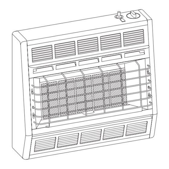
SR-30 SHOWN
AND
UNVENTED
ROOM HEATER
MODELS
SR-6-3
SR-18-3 SR-30-3
This appliance may be installed in an aftermarket,
permanently located, manufactured (mobile)
home, where not prohibited by local codes.
This appliance is only for use with the type of gas
indicated on the rating plate. This appliance is
not convertible for use with other gases.
This is an unvented gas-fired heater. It uses
air (oxygen) from the room in which it is
installed. Provisions for adequate combustion
and ventilation air must be provided. Refer to
page 6.
WARNING: If not installed, operated and
maintained in accordance with the manufacturer's
instructions, this product could expose you to
substances in fuel or from fuel combustion which
can cause death or serious illness.
WATER
VAPOR:
UNVENTED ROOM HEATERS
Water vapor is a by-product of gas combustion. An
unvented room heater produces approximately
one (1) ounce (30ml) of water for every 1,000
BTU's (.3KW's) of gas input per hour. Refer to
page 6.
SR-10-3
A
BY-PRODUCT
OF
Page 1
Advertisement
Chapters
Table of Contents

Related Manuals for Empire Heating Systems SR-6-3


Summary of Contents for Empire Heating Systems SR-6-3
-
Page 1: Installation Instructions
INSTALLATION INSTRUCTIONS OWNER’S MANUAL UNVENTED ROOM HEATER MODELS SR-6-3 SR-10-3 SR-18-3 SR-30-3 SR-30 SHOWN Installer: Leave this manual with the appli- This appliance may be installed in an aftermarket, ance. permanently located, manufactured (mobile) Consumer: Retain this manual for future refer- home, where not prohibited by local codes. -
Page 2: Table Of Contents
TABLe OF COnTenTS SECTION PAGE Important Safety Information ................3 Safety Information for Users of LP Gas ............... 4 Introduction ......................5 Specifications ......................5 Water Vapor: A By-Product of Unvented Room Heaters ........6 Provisions for Adequate Combustion and Ventilation Air ........6 Gas Supply ...................... -
Page 3: Important Safety Information
IMPORTAnT SAFeTy InFORMATIOn THIS IS A HEATING APPLIANCE DO NOT OPERATE THIS APPLIANCE WITHOUT FRONT PANEL INSTALLED. • An unvented room heater having an input rating of SERVICE PERSON. The appliance should be inspected more than 6,000 Btu per hour shall not be installed in a before use and at least annually by a professional service bathroom. -
Page 4: Safety Information For Users Of Lp Gas
SAFeTy InFORMATIOn FOR USeRS OF LP-GAS Propane (LP-Gas) is a flammable gas which can cause fires by point with the members of your household. Someday when and explosions. In its natural state, propane is odorless and there may not be a minute to lose, everyone's safety will depend colorless. -
Page 5: Introduction
InTRODUCTIOn Instructions to Installer Contact the manufacturer or your gas company before changing spud/ 1. Installer must leave instruction manual with owner after installation. orifice size. 2. Installer must have owner fill out and mail warranty card supplied with Qualified Installing Agency unvented room heater. -
Page 6: Water Vapor: A By-Product Of Unvented Room Heaters
WATeR VAPOR: A By-PRODUCT OF UnVenTeD ROOM HeATeRS Water vapor is a by-product of gas combustion. An unvented room The following steps will help insure that water vapor does not heater produces approximately one (1) ounce (30ml) of water for become a problem. -
Page 7: Gas Supply
GAS SUPPLy The gas line can be routed either through the floor or wall. The gas A gas valve and ground joint union should be installed in the gas line opening should be made at this time. Location of the opening line upstream of the gas control to aid in servicing. -
Page 8: Clearances
SR-6 CLeARAnCeS When facing the front of the appliance the following minimum clearances to combustible construction must be maintained. Left side 6 inches (152mm). Right side 6 inches 152mm). Do not install in alcove or closet. Rear wall 0 (0mm) inches. Ceiling 24 inches (610mm). Minimum vertical clearance from a projection above the appliance (shelves, window sills, etc.) 10 inches (254mm). -
Page 9: Clearances
CEILING CEILING 12” MAX WINDOW SILL OR SHELF SIDE WALL (305mm) 24” MIN (610mm) 24” MIN (610mm) 14” MIN 14” MIN 0” (0mm) CLEARANCE (356mm) (356mm) TO REAR WALL 6” MIN 6” MIN (152mm) (152mm) SIDE VIEW 2” MIN 2” MIN (51mm) (51mm) FLOOR... -
Page 10: Clearances
SR-30 CLeARAnCeS When facing the front of the appliance the following CEILING minimum clearances to combustible construction must be maintained. SIDE WALL Left side 8 inches (203mm). Right side 8 inches (203mm). 36” MIN Do not install in alcove or closet. Rear wall 0 inches (0mm). -
Page 11: Wall Mount Installation
WALL MOUNT INSTALLATION (CONT.) On Solid Wall 18” 1. After locating mounting holes, attach (4) #10 x 1" (25mm) (457mm) screws provided into the wall. Do not completely tighten 14” screwheads to the wall, leave a 1/8" (3mm) gap between (356mm) screwheads and wall. -
Page 12: Optional Floor Stand Installation
OPTIOnAL FLOOR STAnD InSTALLATIOn 1. Align clearance holes on floor stand with screw holes on bottom of heater, as shown in Figure 14. 2. Attach floor stand to heater with (4) screws provided with floor stand. 3. Connect the gas line. *Floor stand can not be used in a bathroom or bedroom installation. -
Page 13: Lighting Instructions
LIGHTInG InSTRUCTIOnS FOR yOUR SAFeTy ReAD BeFORe LIGHTInG WARnInG: If you do not follow these instructions exactly, a fire or explosion may result caus- ing property damage, personal injury or loss of life. A. This appliance has a pilot which must be lighted by hand. C. -
Page 14: Main Burner Flame Characteristics
MAIn BURneR FLAMe CHARACTeRISTICS SR-6 Main Burner Flame (Figure 15) 13. Apply air pressure into ceramic plaque(s) to remove dust, lint The main burner flame will have a red-orange glow over the sur- or spider webs. face of the ceramic plaque. The red-orange glow on the surface of 14. -
Page 15: Pilot Flame Characteristics
PILOT FLAMe CHARACTeRISTICS The correct flame will be blue and will extend beyond the 2. Blow air pressure through the holes indicated by the arrows. thermocouple. The flame will surround the thermocouple just below This will blow our foreign materials such as dust, lint and the tip. -
Page 16: Appliance Maintenance
APPLIAnCe MAInTenAnCe Removing Pilot/Thermocouple From Main Burner Assembly Removing Manual Gas Control From Casing Assembly Attention: The thermocouple CAn nOT be replaced as an individual Turn OFF gas supply to the heater. item. you must order a new pilot when replacing thermocouple. Turn OFF electrical supply to the heater if optional blower is installed in heater. -
Page 17: Troubleshooting
TROUBLeSHOOTInG Spark electrode does not produce spark. 4. Main burner does not ignite. Spark electrode broken - replace. Main burner orifice is blocked - clean, see "Main Burner Ignitor wire may not be attached to spark electrode - Flame Characteristics," Page 14. Attention: The number attach. -
Page 18: Parts Lists
PARTS LIST SR-10 SR-6 Index Part Description Index Part Description 13345 CASInG SIDe ASSeMBLy – LeFT 13344 CASInG SIDe ASSeMBLy – LeFT R-2313 PIeZO IGnITOR R-2313 PIeZO IGnITOR R-2328 COnTROL KnOB R-2328 COnTROL KnOB SR-036 COnTROL ROD SR-036 COnTROL ROD SR-126 CASInG BACK SR-177 CASInG BACK SR-008 CASInG SIDe ASSeMBLy –... -
Page 19: Parts Lists
PARTS LIST SR-30 SR-18 INDEx NO. PART NO. DESCRIPTION INDEx NO. PART NO. DESCRIPTION 13346 CASInG SIDe ASSeMBLy - LeFT 13346 CASInG SIDe ASSeMBLy - LeFT SR-004 CASInG BACK SR-068 CASInG BACK R-2313 PIeZO IGnITOR R-2313 PIeZO IGnITOR R-2324 COnTROL KnOB R-2324 COnTROL KnOB SR-036... -
Page 20: Parts View
SR-6 PARTS VIeW Page 20 16942-7-1009... -
Page 21: Sr-10 Parts View
SR-10 PARTS VIeW 16942-7-1009 Page 21... -
Page 22: Parts View
SR-18 PARTS VIeW Page 22 16942-7-1009... -
Page 23: Parts View
SR-30 PARTS VIeW 16942-7-1009 Page 23... -
Page 24: Optional Blower Installation Instructions
OPTIOnAL BLOWeR InSTALLATIOn InSTRUCTIOnS OPTIONAL BLOWERS SRB-18 and SRB-30 for Unvented Room Heaters SR-18 and SR-30 INSTALLING OPTIONAL BLOWER SRB-18 OR SRB-30 11. Attach (1) pin terminal from the on/off switch to (1) socket If heater is installed onto the wall, in order to install the optional terminal from black (hot) wire on motor wire harness. - Page 25 OPTIONAL BLOWER INSTALLATION INSTRUCTIONS (continued) Blower Wheel Excessive Blower Wheel Noise ATTenTIOn! If your blower assembly develops a squeal, hum or The blower wheel will collect lint and could require periodic cleaning. If the air output decreases or the noise level increases, it grinding noise, it indicates dirt or debris on shaft of blower wheel.
-
Page 26: Optional Blower Installation Instructions
OPTIONAL BLOWER INSTALLATION INSTRUCTIONS (continued) PARTS LIST InDeX PART DeSCRIPTIOn R-2396 BLOWER (INCLUDES MOTOR, FAn, AnD FAn HOUSInG) R-2522 On/OFF SWITCH R-2395 WIRe ASSeMBLy 8720161 BUSHING - HEYCO #SR5KN4 VF-068 CORD SeT ASSeMBLy SR-195 BLOWER PAN (SR-18) 8520141 RUBBeR GROMMeT (4 REQUIRED) 8520142 BRASS BUSHING (4 REQUIRED) SR-218... -
Page 27: Master Parts Distributor List
MASTER PARTS DISTRIBUTOR LIST To Order Parts Under Warranty, please contact your local empire dealer. See the dealer locator at www.empirecomfort.com. To provide warranty service, your dealer will need your name and address, purchase date and serial number, and the nature of the problem with the unit. - Page 28 empire Comfort Systems Inc. EMPIRE EMPIRE 918 Freeburg Ave. Belleville, IL 62220 If you have a general question about our products, please e-mail us at info@empirecomfort.com. If you have a service or repair question, please contact your dealer. Comfort Systems www.empirecomfort.com Page 28 16942-7-1009...
- Page 29 INSTRUCCIONES DE INSTALACIÓN MANUAL DEL PROPIETARIO CALENTADOR DE gAS PARA hAbITACIONES MODELOS SR-6-3 SR-10-3 SR-18-3 SR-30-3 SR-30 Se Muestra Este aparato puede instalarse en una casa móvil per- Instalador: Dele estas instrucciones al cliente. manentemente ubicada después de la venta, donde no...
- Page 30 Tabla de COnTenidO SeCCiÓn PÁGina importante información de Securidad ................3 información de Securidad para Usuarios de Gas Propano (lP) ........4 introducción ........................5 Especificaciones ......................5 Vapor de agua: Un Subproducto de Calentadores de Cuarto sin emisión ....6 Provisiones para Combustión de aire adecuados ............
-
Page 31: Importante Información De Securidad
iMPORTanTe infORMaCiÓn de SeGURidad eSTe eS Un aPaRaTO de CalefaCCiÓn nO OPeRe eSTe aPaRaTO Sin el Panel fROnTal inSTaladO. • Un calentador de habitaciones sin ventilación externa que • La instalación y reparación deberá ser hecha por una tenga una capacidad mayor de 6,000 Btu por hora no debe persona de servicio capacitada. -
Page 32: Información De Securidad Para Usuarios De Gas Propano (Lp)
infORMaCiÓn de SeGURidad PaRa USUaRiOS de GaS PROPanO (lP) Gas propano (LP-GAS) es un gas inflamable el cual puede causar punto por punto con los miembros de su casa. algún día cuando fuegos y explosiones. En su estado natural , el propano (LP) no tiene no tenga un minuto que perder, la seguridad de todos dependerá... -
Page 33: Introducción
inTROdUCCiÓn instrucciones al instalador compañía de gas o el fabricante antes de cambiar el tamaño del inyector 1. el instalador debe dejar el manual de instrucciones con el propietario del aparato. después de la instalación. Agencia Calificada de Instalación 2. El instalador debe ver que el propietario llene la tarjeta de garantía que Instalación y reemplazo de tubería de gas, equipo para la utilización de se incluye con el calentador y la mande por correo. -
Page 34: Vapor De Agua: Un Subproducto De Calentadores De Cuarto Sin Emisión
VaPOR de aGUa: Un SUbPROdUCTO de CalenTadOReS de CUaRTO Sin eMiSiÓn el vapor de agua es un subproducto de la combustión de gas. Un agua no se convierta en problema. calentador de habitación sin ventilación externa produce una (1) 1. Asegúrese de que calentador sea del tamaño correcto para la onza (30ml) de agua por cada 1,000 BTU’s (.3KW’s) de entrada aplicación, incluyendo suficiente aire para la combustión y de gas por hora. -
Page 35: Abastecimiento De Gas
abaSTeCiMienTO de GaS Una unión para válvula de gas y para la conexión de tierra deben la línea de gas puede entrar al aparato ya sea a través del piso o de instalarse en la línea de gas contracorriente de la válvula para a través de la pared. -
Page 36: Espacios Libres Del Sr-6
eSPaCiOS libReS del SR-6 Cuando esté de frente al aparato los siguientes espacios libres mínimos a la construcción combustible deben mantenerse. Lado izquierdo 6 pulgadas (152mm). Lado derecho 6 pulgadas (152mm). no instalarlo en un closet o armario. Pared trasera 0 pulgadas (0mm). Techo 24 pulgadas (610mm). Espacio libre vertical mínimo de una proyección arriba del aparato (repisa, antepecho de ventana, etc.) 10 pulgadas (254mm). -
Page 37: Espacios Libres Del Sr-18
TECHO TECHO PARED ANTEPECHO VENTANA O REPISA LATERAL 24” MIN (305mm) (610mm) ANTEPECHO VENTANA O REPISA (610mm) ESPACIO LIBRE A 14” MIN PARED TRASERA (356mm) 6” MIN (356mm) O’(0mm) 6” MIN (152mm) (152mm) VISTA LATERAL 2” MIN (51mm) (51mm) PISO PISO figura 5 (SR-10) figura 6 (SR-10) -
Page 38: Espacios Libres Del Sr-30
eSPaCiOS libReS del SR-30 Cuando esté de frente al aparato los siguientes espacios libres TECHO mínimos a la construcción combustible deben mantenerse. Lado izquierdo 8 pulgadas (203mm). Lado derecho 8 pulgadas PARED LATERAL (203mm). no instalarlo en un closet o armario. Pared trasera 0 pulgadas (0mm). - Page 39 en Pared Maciza 1. Después de ubicar los orificios del montaje, adjunte (4) tornil- (457mm) los #10 x 1" (25mm), que se proveen, en la pared. No apriete (356mm) (51) (51) completamente los tornillos a la pared, deje un espacio de (28mm) 1/8"...
-
Page 40: Installación De Base De Piso Opcional
inSTalaCiÓn de baSe de PiSO OPCiOnal 1. Alinear los orificios de la base con los orificios de los tornil- los en la parte inferior del calentador, como se muestra en la figura 14. 2. Conectar la base al calentador con los (4) tornillos que se proveen. -
Page 41: Instrucciones De Encendido
inSTRUCCiOneS de enCendidO PaRa SU SeGURidad lea anTeS de enCendeR adVeRTenCia: Si usted no sigue estas instrucciones con exactitud, puede provocar incendio o ex- plosión, causando daños a la propiedad, lesión personal o pérdida de vida. A. Este aparato tiene que encenderse manualmente. Cuando •... -
Page 42: Características De La Llama De Quemador Principal
CaRaCTeRíSTiCaS de la llaMa del QUeMadOR PRinCiPal 14. Como las partes son reemplazadas en orden contrario, revisar SR-6 la flama del Quemador (figura 15) si existen fugas de gas en todas las conexiones antes de reem- La flama del quemador tendrá un color rojo - anaranjado resp- plazar la persiana inferior al gabinete. -
Page 43: Características De La Llama Del Piloto
CaRaCTeRíSTiCaS de la llaMa del PilOTO La flama correcta será azúl y se extenderá 1/4" (6mm) más allá 2. Aplicar aire a presión a través de los orificios del piloto del termopar. La flama se ubicará alrededor del termopar, un poco indicados por las flechas. -
Page 44: Mantenimiento Del Aparato
ManTeniMienTO del aPaRaTO Para Remover el Piloto/Termopar del ensamblaje Principal del Que- 3. Remover la persiana inferior del gabinete (2 tornillos). mador 4. Remover el reflector del gabinete (2 tornillos). atención: el termopar nO PUede cambiarse por si sólo. Ud. debe pedir 5. -
Page 45: Lista De Partes De Los Sr-6 Y Sr-10
liSTa de PaRTeS POR faVOR TOMe nOTa: Al ordenar partes, es muy importante que el número de parte y la descripción de la misma coincidan. SR-6 SR-10 indeX PaRT indeX PaRT nUMbeR nUMbeR deSCRiPTiOn nUMbeR nUMbeR deSCRiPTiOn 13344 Gabinete Latereal Izquierdo 13345 Gabinete Latereal Izquierdo R-2313... - Page 46 liSTa de PaRTeS SR-18 SR-30 indeX PaRT indeX PaRT nUMbeR nUMbeR deSCRiPTiOn nUMbeR nUMbeR deSCRiPTiOn 13346 Gabinete Latereal Izquierdo 13346 Gabinete Latereal Izquierdo SR-068 Gabinete Trasero SR-004 Gabinete Trasero R-2313 encendedor Piezo R-2313 encendedor Piezo R-2324 botón Control R-2324 botón Control SR-036 Varilla Control SR-036...
-
Page 47: Vista De Partes Del Sr-6
SR-6 — ViSTa de PaRTeS 16942-2-1009 Page 19... -
Page 48: Vista De Partes Del Sr-10
SR-10 — ViSTa de PaRTeS Page 20 16942-2-1009... -
Page 49: Vista De Partes Del Sr-18
SR-18 — ViSTa de PaRTeS 16942-2-1009 Page 21... -
Page 50: Vista De Partes Del Sr-30
SR-30 — ViSTa de PaRTeS Page 22 16942-2-1009... -
Page 51: Ventilador Opcional Instrucciones De Instalación
VenTiladOR OPCiOnal inSTRUCCiOneS de inSTalaCiÓn SRb-18 y SRb-30 para Calentadores de Habitación SR-18 y SR-30 inSTalaCiÓn VenTiladOR OPCiOnal SRb-18 O SRb-30 13. estando el calentador en posición vertical, colocar la apertura de salida de aire de la cubierta del ventilador hacia abajo. Ubicar la Si el calentador se instala en la pared, debe ser removido a fin de instalar pestaña inferior de la cubierta del ventilador sobre la orilla superior el ventilador opcional. - Page 52 VenTiladOR OPCiOnal (continua) AISLANTE NEGRO ACANALADO Cables AISLANTE NEGRO LISO el aparato debe estar conectado a tierra de acuerdo al “national electrical Code” ANSI/NFPA 70. Este Ventilador viene equipado con un enchufe CABLE ENTRADA VERDE aislado de tierra con tres puntas para su protección contra sacudidas peligro- SPT-3 sas y debe conectarse directamente a un tomacorriente del mismo tipo.
Need help?
Do you have a question about the SR-6-3 and is the answer not in the manual?
Questions and answers