Table of Contents
Advertisement
WARNING: If the information in this manual
is not followed exactly, a fire or explosion may
result causing property damage, personal in-
jury or loss of life.
– Do not store or use gasoline or other flammable
vapors and liquids in the vicinity of this or any
other appliance.
– WHAT TO DO IF YOU SMELL GAS
• Do not try to light any appliance.
• Do not touch any electrical switch; do not use
any phone in your building.
• Immediately call your gas supplier from a
neighbor's phone. Follow the gas supplier's
instructions.
• If you cannot reach your gas supplier, call the
fire department.
– Installation and service must be performed by
a qualified installer, service agency or the gas
supplier.
Page 1
INSTALLATION INSTRUCTIONS
OWNER'S MANUAL
RH-50-6 Shown
AND
VENTED
ROOM HEATER
MODELS
RH-50-6
RH-50C-1
EFFECTIVE DATE
APRIL 2006
Installer: Please leave these instructions with the
consumer.
Consumer: Please retain these instructions for
future use.
WARNING: If not installed, operated and main-
tained in accordance with the manufacturer's in-
structions, this product could expose you to sub-
stances in fuel or from fuel combustion which can
cause death or serious illness.
RH-65-6
RH-65C-1
12822-3-0406
Advertisement
Table of Contents

Subscribe to Our Youtube Channel
Related Manuals for Empire Heating Systems RH-50-6


Summary of Contents for Empire Heating Systems RH-50-6
-
Page 1: Installation Instructions
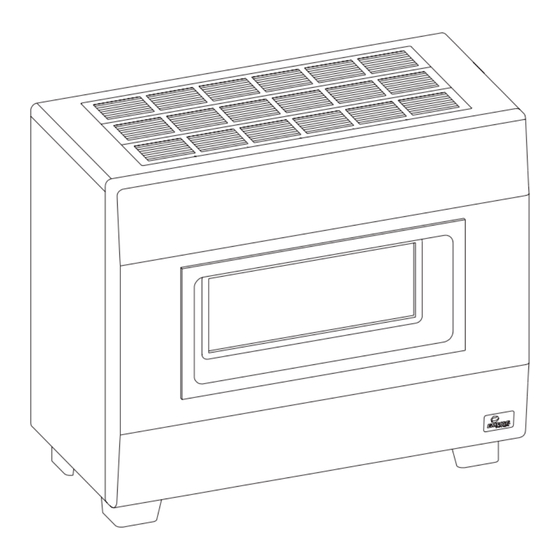
INSTALLATION INSTRUCTIONS OWNER’S MANUAL VENTED ROOM HEATER MODELS RH-50-6 RH-65-6 RH-50C-1 RH-65C-1 RH-50-6 Shown WARNING: If the information in this manual is not followed exactly, a fire or explosion may result causing property damage, personal in- EFFECTIVE DATE jury or loss of life. APRIL 2006 –... -
Page 2: Table Of Contents
TABLE OF CONTENTS SECTION PAGE Important Safety Information ....................3 Safety Information for Users of LP Gas .................4 Introduction ..........................5 Specifications .........................5 Gas Supply ..........................6 Clearances ..........................7 Venting ...........................7 Vent Safety Shutoff System ....................8 Reversible Vertical or Horizontal Diverter ................8 Thermostat Operation ......................8 Lighting Instructions ......................9 Pilot Flame Characteristics ....................10 Main Burner Flame Characteristics ..................10... -
Page 3: Important Safety Information
IMPORTANT SAFETY INFORMATION THIS IS A HEATING APPLIANCE DO NOT OPERATE THIS APPLIANCE WITHOUT FRONT PANEL INSTALLED. • Due to high temperatures, the room heater should be located • DO NOT put anything around the heater that will ob- out of traffic and away from furniture and draperies. struct the flow of combustion and ventilation air. -
Page 4: Safety Information For Users Of Lp Gas
SAFETY INFORMATION FOR USERS OF LP-GAS Propane (LP-Gas) is a flammable gas which can cause fires point with the members of your household. Someday, when and explosions. In its natural state, propane is odorless and there may not be a minute to lose, everyone’s safety will de- colorless. -
Page 5: Introduction
INTRODUCTION Introduction The base referred to above does not mean the fire-proof base as Always consult your local Building Department regarding regu- used on wood stoves. The protection is primarily for rugs that may lations, codes or ordinances which apply to the installation of a be extremely thick and light-color tile that can discolor. -
Page 6: Gas Supply
GAS SUPPLY Recommended Gas Pipe Diameter checked for leaks by the installer. This should be done with a soap solution watching for bubbles on all exposed connections, and if Pipe Length Schedule 40 Pipe Tubing, Type L unexposed, a pressure test should be made. (Feet) Inside Diameter Outside Diameter... -
Page 7: Clearances
CLEARANCES Clearances: When facing the front of the room heater the mini- Do not install in alcove or closet. mum clearances to combustible construction (material) are the No horizontal projection above heater permitted within 55 inches following: (140 cm). Ceiling 55 inches (140cm) Left side - 6 inches (152mm) Draft hood to rear wall 2 inches (51 mm) Right side - 6 inches (152mm) -
Page 8: Vent Safety Shutoff System
VENT SAFETY SHUTOFF SYSTEM This heater must be properly connected to a venting system. This This room heater is equipped with a vent safety switch. The vent heater is equipped with a vent safety shutoff system. safety switch will cause gas flow to the pilot to “shut off” due to improper venting or a blocked flue. -
Page 9: Lighting Instructions
LIGHTING INSTRUCTIONS FOR YOUR SAFETY READ BEFORE LIGHTING WARNING: If you do not follow these instructions exactly, a fire or explosion may result causing property damage, personal injury or loss of life. A. This appliance has a pilot which must be lighted by hand. •... -
Page 10: Pilot Flame Characteristics
PILOT FLAME CHARACTERISTICS The correct flame will be almost horizontal, blue and will extend past the thermocouple 1/4” (6mm). The flame will surround the thermocouple just below the tip. On Propane (LP-gas) slight yellow might occur where the pilot flame and the burner flame meet. Natural gas pilots require adjusting when the inlet pressure is above 5”... -
Page 11: Maintenance
MAINTENANCE Cleaning Pilot Burner Primary Air Adjustment After use, cleaning of the pilot burner may be required for the 1. A primary air adjustment bolt is located on left, front of burner throat. proper flame. The pilot orifice can be cleaned with high pressure The bolt can be screwed into burner throat to REDUCE primary air or by placing under running water. -
Page 12: How To Order Repair Parts
HOW TO ORDER REPAIR PARTS Parts can be ordered only through your service person or dealer. For best results, the service person or dealer should order parts through the distributor. Parts can be shipped directly to the service person/dealer. All parts listed in the Parts List have a Part Number. When ordering parts, first obtain the Model Number from the name plate on your equipment. -
Page 13: Parts View Rh-50 & Rh-65
PARTS VIEW RH-50 & RH-65 Page 13 12822-3-0406... -
Page 14: Parts List Rh-50C & Rh-65C
PARTS LIST RH-50C & RH-65C PLEASE NOTE: When ordering parts, it is very important that part number and description of part coincide. INDEX PART DESCRIPTION INDEX PART DESCRIPTION NUMBER NUMBER 11723 Diverter Assembly R-6126 Electrode and Wire Assembly RH-802 Down Draft Shield (RH-50C-1 NAT & LPG) 11712 Pilot Tubing (RH-50C-1) RH-851... -
Page 15: Parts View Rh-50C & Rh-65C
PARTS VIEW RH-50C & RH-65C Page 15 12822-3-0406... -
Page 16: Optional Blower Installation Instructions
OPTIONAL BLOWER INSTALLATION INSTRUCTIONS FRB-3 For Vented Room Heaters Models RH-50-(1, 2, 3, 4, 5, 6) RH-50C-1 RH-65-(1, 2, 3, 4, 5, 6) RH-65C-1 Figure 2 Figure 1 Installing Optional Blower 1. Remove rear shield (2 screws) and bottom reflector (4 screws). (See Figure 1) 2. - Page 17 Attention: Wiring harness on blower is factory assembled and Wiring installed. If wiring harness becomes disassembled, use the fol- The appliance, when installed, must be electrically grounded in ac- lowing steps to reassemble the wiring harness. cordance with local codes or, in the absence of local codes, with the 1.
-
Page 18: Service Notes
SERVICE NOTES 12822-3-0406 Page 18... - Page 19 SERVICE NOTES Page 19 12822-3-0406...
- Page 20 SERVICE NOTES Empire Comfort Systems, Inc. 918 Freeburg Ave. Belleville, IL 62220 PH: 618-233-7420 or 800-851-3153 FAX: 618-233-7097 or 800-443-8648 info@empirecomfort.com www.empirecomfort.com 12822-3-0406 Page 20...
Need help?
Do you have a question about the RH-50-6 and is the answer not in the manual?
Questions and answers