Table of Contents
Advertisement
Quick Links
Installer:
Leave this manual with the appliance.
Consumer: Retain this manual for future reference.
WARNING: If the information in these instructions
are not followed exactly, a fire or explosion may
result causing property damage, personal injury or
loss of life.
— Do not store or use gasoline or other flammable
vapors and liquids in the vicinity of this or any
other appliance.
— WHAT TO DO IF YOU SMELL GAS
•
Do not try to light any appliance.
•
Do not touch any electrical switch; do not use
any phone in your building.
•
Immediately call your gas supplier from a
neighbor's phone. Follow the gas supplier's
instructions.
•
If you cannot reach your gas supplier, call the
fire department.
— Installation and service must be performed by a
qualified installer, service agency or the gas sup-
plier.
INSTALLATION INSTRUCTIONS
OWNER'S MANUAL
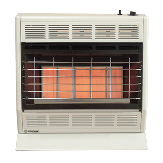
SR-30 SHOWN
AND
UNVENTED
ROOM HEATER
MODELS
SR-6-4
SR-18-4 SR-30-4
This appliance may be installed in an aftermarket,
permanently located, manufactured (mobile) home,
where not prohibited by local codes.
This appliance is only for use with the type of gas
indicated on the rating plate. This appliance is not
convertible for use with other gases.
This is an unvented gas-fired heater. It uses air
(oxygen) from the room in which it is installed.
Provisions for adequate combustion and ventilation
air must be provided. Refer to page 6.
WARNING: If not installed, operated and maintained
in accordance with the manufacturer's instructions,
this product could expose you to substances in fuel
or from fuel combustion which can cause death or
serious illness.
WATER VAPOR: A BY-PRODUCT OF UNVENTED
ROOM HEATERS
Water vapor is a by-product of gas combustion.
An unvented room heater produces approximately
one (1) ounce (30ml) of water for every 1,000 BTU's
(.3KW's) of gas input per hour. Refer to page 6.
SR-10-4
Page 1
Advertisement
Table of Contents

Related Manuals for Empire Heating Systems SR-6-4


Summary of Contents for Empire Heating Systems SR-6-4
- Page 1 INSTALLATION INSTRUCTIONS OWNER’S MANUAL UNVENTED ROOM HEATER MODELS SR-6-4 SR-10-4 SR-18-4 SR-30-4 SR-30 SHOWN Installer: Leave this manual with the appliance. This appliance may be installed in an aftermarket, Consumer: Retain this manual for future reference. permanently located, manufactured (mobile) home, where not prohibited by local codes.
-
Page 2: Table Of Contents
TABLe OF COnTenTS SECTION PAGE Important Safety Information ..............3 Safety Information for Users of LP Gas ............ 4 Introduction ....................5 Specifications ................... 5 Water Vapor: A By-Product of Unvented Room Heaters ......6 Provisions for Adequate Combustion and Ventilation Air ......6 Gas Supply .................... -
Page 3: Important Safety Information
IMPORTAnT SAFeTy InFORMATIOn THIS IS A HEATING APPLIANCE DO NOT OPERATE THIS APPLIANCE WITHOUT FRONT PANEL INSTALLED. • Installation and repair should be done by a qUALIFIED DANGER: Indicates a hazardous situation which, if not SERVICE PERSON. The appliance should be inspected avoided, will result in death or serious injury. -
Page 4: Safety Information For Users Of Lp Gas
SAFeTy InFORMATIOn FOR USeRS OF LP-GAS Propane (LP-Gas) is a flammable gas which can cause fires point with the members of your household. Someday when and explosions. In its natural state, propane is odorless and there may not be a minute to lose, everyone's safety will depend colorless. -
Page 5: Introduction
InTRODUCTIOn Instructions to Installer Well Head Gas Installations 1. Installer must leave instruction manual with owner after Some natural gas utilities use “well head” gas. This may affect the installation. Btu output of the unit. Contact the gas company for the heating 2. -
Page 6: Water Vapor: A By-Product Of Unvented Room Heaters
WATeR VAPOR: A By-PRODUCT OF UnVenTeD ROOM HeATeRS Water vapor is a by-product of gas combustion. An unvented room The following steps will help insure that water vapor does not heater produces approximately one (1) ounce (30ml) of water for become a problem. -
Page 7: Gas Supply
GAS SUPPLy The gas line can be routed either through the floor or wall. The gas the national Fuel Gas Code that a drip line be installed near the gas line opening should be made at this time. Location of the opening inlet. -
Page 8: Clearances
SR-6 CLeARAnCeS When facing the front of the appliance the following minimum clearances to combustible construction must be maintained. Left side 6 inches (152mm). Right side 6 inches 152mm). Do not install in alcove or closet. Rear wall 0 (0mm) inches. Ceiling 24 inches (610mm). Minimum vertical clearance from a projection above the appliance (shelves, window sills, etc.) 10 inches (254mm). -
Page 9: Clearances
CEILING CEILING 12” MAX WINDOW SILL OR SHELF SIDE WALL (305mm) 24” MIN (610mm) 24” MIN (610mm) 14” MIN 14” MIN 0” (0mm) CLEARANCE (356mm) (356mm) TO REAR WALL 6” MIN 6” MIN (152mm) (152mm) SIDE VIEW 2” MIN 2” MIN (51mm) (51mm) FLOOR... -
Page 10: Clearances
SR-30 CLeARAnCeS When facing the front of the appliance the following minimum CEILING clearances to combustible construction must be maintained. Left side 8 inches (203mm). Right side 8 inches (203mm). SIDE WALL Do not install in alcove or closet. Rear wall 0 inches (0mm). Ceiling 36 inches (914mm). Minimum vertical clearance from a projection above the 36”... -
Page 11: Wall Mount Installation
WALL MOUNT INSTALLATION (CONT.) On Solid Wall 18” 1. After locating mounting holes, attach (4) #10 x 1" (25mm) screws (457mm) provided into the wall. Do not completely tighten screwheads 14” to the wall, leave a 1/8" (3mm) gap between screwheads and (356mm) wall. -
Page 12: Optional Floor Stand Installation
OPTIOnAL FLOOR STAnD InSTALLATIOn 1. Align clearance holes on floor stand with screw holes on bottom of heater, as shown in Figure 14. 2. Attach floor stand to heater with (4) screws provided with floor stand. 3. Connect the gas line. *Floor stand can not be used in a bathroom or bedroom installation. -
Page 13: Lighting Instructions
LIGHTInG InSTRUCTIOnS FOR yOUR SAFeTy ReAD BeFORe LIGHTInG WARnInG: If you do not follow these instructions exactly, a fire or explosion may result causing property damage, personal injury or loss of life. A. This appliance has a pilot which must be lighted by tions. -
Page 14: Main Burner Flame Characteristics
MAIn BURneR FLAMe CHARACTeRISTICS SR-6 Main Burner Flame (Figure 15) The main burner flame will have a red-orange glow over the sur- face of the ceramic plaque. The red-orange glow on the surface of the ceramic plaque will have a pattern in the shape of a number 1. -
Page 15: Pilot Flame Characteristics
PILOT FLAMe CHARACTeRISTICS The correct flame will be blue and will extend beyond the Blow air pressure through the holes indicated by the arrows. thermocouple. The flame will surround the thermocouple just below This will blow our foreign materials such as dust, lint and spider the tip. -
Page 16: Appliance Maintenance
APPLIAnCe MAInTenAnCe Removing Pilot/Thermocouple From Main Burner Assembly Remove reflector from casing assembly (2 screws). Attention: The thermocouple CAn nOT be replaced as an individual Disconnect inlet supply tubing, outlet supply tubing, pilot supply item. you must order a new pilot when replacing thermocouple. tubing and thermocouple lead from manual gas control. -
Page 17: Troubleshooting
TROUBLeSHOOTInG Spark electrode does not produce spark. Main burner does not ignite. Spark electrode broken - replace. Main burner orifice is blocked - clean, see "Main Burner Ignitor wire may not be attached to spark electrode - Flame Characteristics," Page 14. Attention: The number attach. -
Page 18: Parts Lists
PARTS LIST SR-6 SR-10 Index Part Description Index Part Description 13344 CASInG SIDe ASSeMBLy – LeFT 13345 CASInG SIDe ASSeMBLy – LeFT R-2313 PIeZO IGnITOR R-2313 PIeZO IGnITOR R-2328 COnTROL KnOB R-2328 COnTROL KnOB SR-036 COnTROL ROD SR-036 COnTROL ROD SR-126 CASInG BACK SR-177... - Page 19 PARTS LIST SR-30 SR-18 INDEx NO. PART NO. DESCRIPTION INDEx NO. PART NO. DESCRIPTION 13346 CASInG SIDe ASSeMBLy - LeFT 13346 CASInG SIDe ASSeMBLy - LeFT SR-004 CASInG BACK SR-068 CASInG BACK R-2313 PIeZO IGnITOR R-2313 PIeZO IGnITOR R-2324 COnTROL KnOB R-2324 COnTROL KnOB SR-036...
-
Page 20: Parts View
SR-6 PARTS VIeW Page 20 35963-0-0615... -
Page 21: Parts View
SR-10 PARTS VIeW 35963-0-0615 Page 21... -
Page 22: Parts View
SR-18 PARTS VIeW Page 22 35963-0-0615... -
Page 23: Parts View
SR-30 PARTS VIeW 35963-0-0615 Page 23... -
Page 24: Optional Blower Installation Instructions
OPTIOnAL BLOWeR InSTALLATIOn InSTRUCTIOnS OPTIONAL BLOWERS SRB-18 and SRB-30 for Unvented Room Heaters SR-18 and SR-30 INSTALLING OPTIONAL BLOWER SRB-18 OR SRB-30 side of the blower housing with (1) screw provided with the If heater is installed onto the wall, in order to install the optional optional blower. - Page 25 OPTIONAL BLOWER INSTALLATION INSTRUCTIONS (continued) Blower Wheel Excessive Blower Wheel Noise ATTenTIOn! If your blower assembly develops a squeal, hum or The blower wheel will collect lint and could require periodic grinding noise, it indicates dirt or debris on shaft of blower wheel. cleaning.
- Page 26 OPTIONAL BLOWER INSTALLATION INSTRUCTIONS (continued) PARTS LIST InDeX PART DeSCRIPTIOn R-2396 BLOWER (INCLUDES MOTOR, FAN, AnD FAn HOUSInG) R-2522 On/OFF SWITCH R-2395 WIRe ASSeMBLy 8720161 BUSHING - HEYCO #SR5KN4 VF-068 CORD SeT ASSeMBLy SR-195 BLOWER PAN (SR-18) 8520141 RUBBeR GROMMeT (4 REQUIRED) 8520142 BRASS BUSHING (4 REQUIRED) SR-218...
-
Page 27: Master Parts Distributor List
MASTER PARTS DISTRIBUTOR LIST To Order Parts Under Warranty, please contact your local empire dealer. See the dealer locator at www.empirecomfort. com. To provide warranty service, your dealer will need your name and address, purchase date and serial number, and the nature of the problem with the unit. - Page 28 empire Comfort Systems Inc. EMPIRE EMPIRE 918 Freeburg Ave. Belleville, IL 62220 If you have a general question about our products, please e-mail us at info@empirecomfort.com. If you have a service or repair question, please contact your dealer. Comfort Systems www.empirecomfort.com Page 28 35963-0-0615...
Need help?
Do you have a question about the SR-6-4 and is the answer not in the manual?
Questions and answers