Table of Contents
Advertisement
Quick Links
Advertisement
Table of Contents

Related Manuals for LevelOne GSW-2453


Summary of Contents for LevelOne GSW-2453
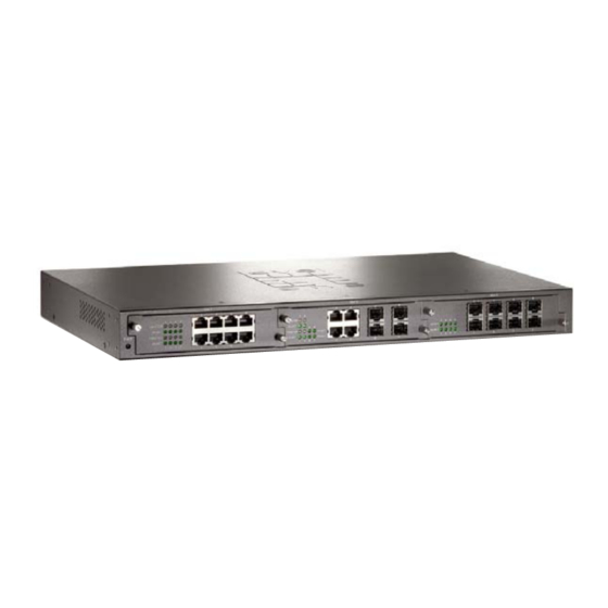
- Page 1 GSW-2453 Gigabit Chassis switch User Guide...
-
Page 3: Table Of Contents
Contents 1. INTRODUCTION ......................1 Features .......................... 1 Package Contents ......................2 Ethernet Switching Technology ..................2 2. HARDWARE DESCRIPTION ..................4 Physical Dimension ......................4 Front Panel ........................4 LED Indicators ........................ 4 Rear Panel ........................6 Desktop Installation ......................6 Rack-mounted Installation .................... -
Page 5: Introduction
1. Introduction GSW-2453, 3-slot Gigabit Chassis switch, is a modular Switch that can be used to build high-performance switched workgroup networks. This switch store-and-forward device that offers low latency for high-speed networking. The Switch is targeted at workgroup, department or backbone computing environment. -
Page 6: Package Contents
Rack-mounted Kit User Guide Figure 1-2. Package Contents Compare the contents of your GSW-2453 package with the standard checklist above. If any item is missing or damaged, please contact your local dealer for service. Ethernet Switching Technology Ethernet Switching Technology dramatically boosted the total bandwidth of a network,... - Page 7 transmissions. This revolutionized networking. First, by allowing two-way, simultaneous transmissions over the same port (Full-duplex), which essentially doubled the bandwidth. Second, by reducing the collision domain to a single switch-port, which eliminated the need for carrier sensing. Third, by using the store-and-forward technology’s approach of inspecting each packet to intercept corrupt or redundant data, switching eliminated unnecessary transmission that slow the network.
-
Page 8: Hardware Description
2. Hardware Description This Section mainly describes the hardware of the GSW-2453, and gives a physical and functional overview of this chassis switch. Physical Dimension The GSW-2453 physical dimension is 440mm(W) x 280mm(D) x 44mm(H). Front Panel The Front Panel of the GSW-2453 consists of 3 module slots. - Page 9 System Status Description Green Power On Power Power is not connected Gigabit Copper Module Status Description Green In 1000Mpbs speed 1000/100 Orange In 100Mbps speed In 10Mbps or no device is connected. Green The port is connecting with the device. LK/ACT Blinks The port is receiving or transmitting data.
-
Page 10: Rear Panel
Rear Panel The 3-pronged power plug, 2 fans, power switching is located at the rear panel of the GSW-2453 as shown in Figure 2-2. The switch will work with AC power in the range of 100-240V AC, 50-60Hz. Figure 2-2. The Rear Panel... - Page 11 Position one bracket to align with the holes on one side of the switch and secure it with the smaller bracket screws. Then attach the remaining bracket to the other side of the Switch. After attached both mounting brackets, position the switch in the rack by lining up the holes in the brackets with the appropriate holes on the rack.
-
Page 12: Network Application
3. Network Application GSW-2453 is designed as a segment switch. That is, with its large address table (4000 MAC address) and high performance, it is ideal for interconnecting networking segments. PC, workstations, and servers can communicate each other by directly connecting with 3-slot Gigabit Chassis s switch. -
Page 13: Troubleshooting
4. Troubleshooting This section is intended to help you solve the most common problems on the GSW-2453. Incorrect connections The switch port can auto detect straight or crossover cable when you link switch with other Ethernet device. For the UTP connector should use correct UTP or STP cable, 10/100Mbps port use 2 pairs twisted cable and Gigabit 1000T port use 4 pairs twisted cable. -
Page 14: Diagnosing Led Indicators
at any time. Data path loops will cause broadcast storms that will severely impact your network performance. Diagnosing LED Indicators The Switch can be easily monitored through panel indicators to assist in identifying problems, which describes common problems you may encounter and where you can find possible solutions. -
Page 15: Technical Specification
5. Technical Specification This section provides the specifications of the GSW-2453 and the following table lists these specifications. IEEE802.3 10Base-T IEEE802.3u 100Base-TX Standard IEEE802.3z Gigabit fiber IEEE802.3ab 1000Base-T Switch architecture Store and forward switch architecture System: Power Per RJ-45 port: 1000/100Mbps, Link/Activity, Full... - Page 16 8-port Gigabit copper module(MDU-2453T) Expansion module 8 MINI GBIC module (MDU-2453M) 4 Gigabit copper+4 MiniGBIC module (MDU-2453TM) MAC address Packet Buffer 2 Mbits Dimensions 440mm(W) x 280mm(D) x 44mm(H) Power Supply 100~240VAC, 50 /60Hz, 0.8A (maximum) 2 x DC cooling fan Ventilation -5 ℃...
Need help?
Do you have a question about the GSW-2453 and is the answer not in the manual?
Questions and answers