AMX Mio Modero Prestige Quick Start Manual
Keypad
Hide thumbs
Also See for Mio Modero Prestige:
- Operation/reference manual (28 pages) ,
- Operation/reference manual (34 pages)
Advertisement
Quick Links
Overview
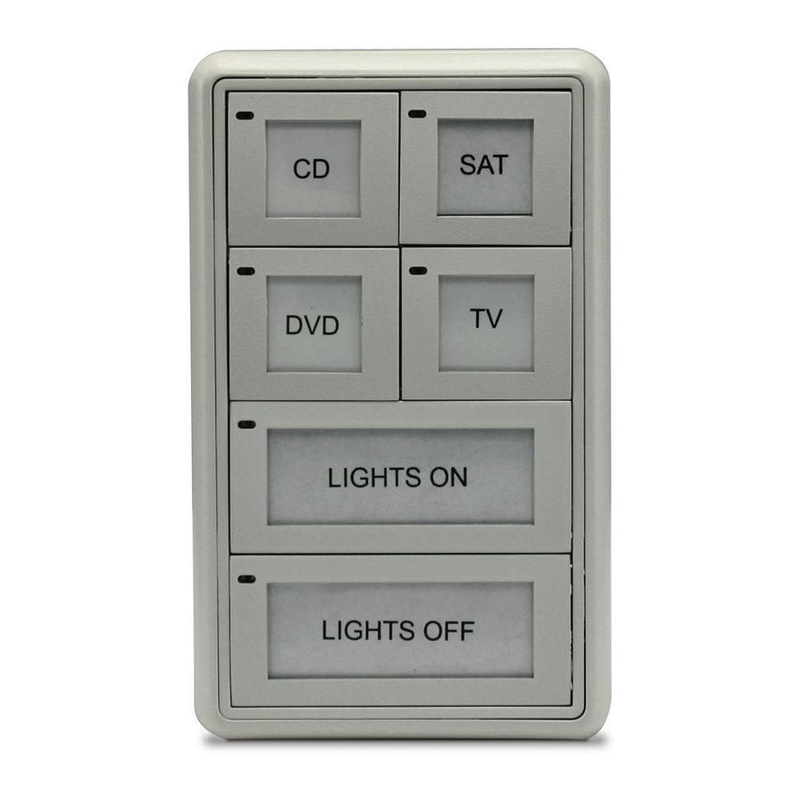
The Mio Modero Prestige (FG5798-01xx, single style; FG5798-02xx, double style; xx
indicates color selection) provides a wide range of control capabilities in the form of
keypads that are as adept as they are elegant. Each device is available as single style
(8 button max) or double style (16 button max).
You need KeypadBuilder to properly program these devices. The application and
documentation are available from www.amx.com.
FIG. 1
Mio Modero Prestige
Specifications
The Mio Modero device family keypad specifications are as follows:
Specifications
Power:
12 vDC, 70 - 230 mA (range depending on device type and number of
buttons)
Front Panel
• Pushbuttons - a maximum of 8 buttons on the single style and 16
buttons on the double style, with a direct LED light.
Components:
Rear Panel
• DIP switch - 8 position mini DIP switch used to set the device address
for the keypad on the AXlink Bus.
Components:
• Wiring connection - 4 pin 3.5mm Phoenix AXlink connector.
Dimensions
• Single style - 4.46" x 2.71" x .57" (113.28 mm x 68.83 mm x 14.48 mm)
• Double style - 4.46" x 4.39" x .57" (113.28 mm x 111.51 mm x 14.48
(HWD):
mm)
Weight
.25 lbs (.11 kg) - .50 lbs (.23 kg) Style and number of buttons will decide
(range):
weight.
Operating
• Operating Temperature: 0° to 50° C (32° to 122° F)
Environment:
• Storage Temperature: -10° to 70° C (14° to 158° F)
Mounting:
Mounts into US and a majority of International single gang back boxes.
Included
• Single style mounting kit (KA-5795-01)
• Double style mounting kit (KA-5795-02)
Accessories:
• Mylar kit - Sheets of common menu items and icons for creating inserts
for single and double buttons.
Available in either black, white, or beige.
91-5798-01WH = White
91-5798-01BG = Beige
91-5798-01BL = Black)
• Phoenix Connector (41-5045)
Optional
• Accent Frame (for some larger wallboxes):
Prestige Colors (xx indicates color selection) -
Accessories:
FG5795-08xx (single button); FG5795-09xx (double button)
• Custom buttons:
Prestige Colors (xx indicates color selection) - FG5798-05xx (4
single buttons); FG5798-06xx (2 double buttons)
Available Color Schemes
The Mio Modero device family is available in a range of colors. The Prestige supports
these color schemes, Black (BL), White (WH), and Beige (BG).
Mounting Frame
Face Plate
Capped Buttons
Mio Modero
Installation
Note: Before touching the device, discharge the static electricity from your body by
touching a grounded metal object.
The basic front and rear components of the Mio Modero are as follows:
LED
Prestige
Button
Button
Window
Screw
holes
(Front Single)
Screw
holes
PWR+
(Rear Double)
FIG. 2
Mio Modero Front and Rear Components
Changing Buttons
The Mio Modero Prestige ships with sheets of common menu items and icons for
creating inserts for single and double buttons.
1.
If connected, disconnect the power supply.
2.
Place a flathead screwdriver in the notch at the bottom right of the Mio Modero,
and pry the faceplate from the mounting frame.
3.
On the back of the faceplate locate the button access points, outlined with white
circles. Using a straightened paperclip, poke through the button access points
until the buttons pop free.
4.
The Prestige buttons are comprised of three parts, the frame, window, and back
insert. From the front of the button, use your thumb to poke the window and back
insert out of the frame. See FIG. 3.
Back Insert
Printed
Label
FIG. 3
Prestige Button Components
5.
Snap the widow into the frame and then place the printed labels inside each
button.
6.
Snap the back inset to the window and frame.
7.
Insert the buttons into their proper location on the faceplate.
8.
If the power supply was disconnected in Step 1, reconnect and return power to
the device.
9.
Snap the faceplate on the mounting frame.
Be certain to reprogram the Mio Modero to match the new button arrangement; use
KeypadBuilder to assign the locations. See the KeypadBuilder Instruction Manual
available at www.amx.com.
Quick Start Guide
Prestige
®
Keypad
AXlink
3.5 mini Phoenix
connector
PWR+
8 position mini
DIP switch
Notch to pry
faceplate free
(Rear Single)
8 position mini
DIP switch
AXlink
3.5 mini Phoenix
connector
Notch to pry
faceplate free
Window
Frame
Advertisement

Related Manuals for AMX Mio Modero Prestige


Summary of Contents for AMX Mio Modero Prestige
-
Page 1: Specifications
FIG. 2 Mio Modero Front and Rear Components Changing Buttons The Mio Modero Prestige ships with sheets of common menu items and icons for creating inserts for single and double buttons. If connected, disconnect the power supply. Place a flathead screwdriver in the notch at the bottom right of the Mio Modero, and pry the faceplate from the mounting frame. -
Page 2: Setting The Axlink Device Number
©2009 AMX. All rights reserved. AMX and the AMX logo are registered trademarks of AMX. AMX reserves the right to alter specifications without notice at any time. 3000 RESEARCH DRIVE, RICHARDSON, TX 75082 • 800.222.0193 • fax 469.624.7153 • technical support 800.932.6993 • www.amx.com Mounting Procedures AMX recommends mounting the Mio Modero in a standard one-gang wallbox, a conduit box per NEC specs section 370, with a minimum internal clearance of 2-5/8"...
Need help?
Do you have a question about the Mio Modero Prestige and is the answer not in the manual?
Questions and answers