Table of Contents
Advertisement
Quick Links
CAUTION, MICROWAVE RADIATION ............................................................................................................. 1
WARNING .......................................................................................................................................................... 1
PRODUCT SPECIFICATIONS ......................................................................................................................... 2
GENERAL INFORMATION ................................................................................................................................ 2
APPEARANCE VIEW ....................................................................................................................................... 3
OPERATION SEQUENCE ................................................................................................................................ 4
FUNCTION OF IMPORTANT COMPONENTS ................................................................................................ 5
SERVICING ...................................................................................................................................................... 6
TEST PROCEDURE ......................................................................................................................................... 8
TOUCH CONTROL PANEL ............................................................................................................................. 13
COMPONENT REPLACEMENT AND ADJUSTMENT PROCEDURE ........................................................... 18
MICROWAVE MEASUREMENT .................................................................................................................... 24
WIRING DIAGRAM ......................................................................................................................................... 25
PICTORIAL DIAGRAM ................................................................................................................................... 26
POWER UNIT CIRCUIT .................................................................................................................................. 27
CPU UNIT CIRCUIT ........................................................................................................................................ 28
PRINTED WIRING BOARD ............................................................................................................................. 29
PARTS LIST ................................................................................................................................................... 30
MODEL
In interests of user-safety the oven should be restored to its original
condition and only parts identical to those specified should be used.
TABLE OF CONTENTS
SHARP CORPORATION
35
S7304R450HPJ/
MICROWAVE OVEN
R-450H
R-450H
Page
Advertisement
Table of Contents

Related Manuals for Sharp R-450H


Summary of Contents for Sharp R-450H
-
Page 1: Table Of Contents
R-450H SERVICE MANUAL S7304R450HPJ/ MICROWAVE OVEN R-450H MODEL In interests of user-safety the oven should be restored to its original condition and only parts identical to those specified should be used. TABLE OF CONTENTS Page CAUTION, MICROWAVE RADIATION ......................1 WARNING ................................ - Page 2 R-450H...
-
Page 3: Caution Microwave Radiation
MICROWAVE OVEN APPEARANCE VIEW R-450H GENERAL IMPORTANT INFORMATION This Manual has been prepared to provide Sharp Corp. Service OPERATING SEQUENCE engineers with Operation and Service Information. It is recommended that service engineers carefully study the entire text of this manual, so they will be qualified to render FUNCTION OF IMPORTANT satisfactory customer service. -
Page 4: Product Specifications
R-450H PRODUCT SPECIFICATIONS ITEM DESCRIPTION Power Requirements 230 - 240 Volts 50 Hertz Single phase, 3 wire earthed Power Consumption 1.65 kW Power Output 1200 watts nominal of RF microwave energy (IEC Test Procedure) Operating frequency 2450 MHz Case Dimensions... -
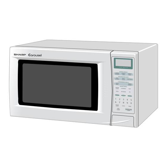
Page 5: Appearance View
R-450H APPEARANCE VIEW 1. Ventilation openings 2. Oven lamp 3. Door hinges 4. Door safety latches 5. See through door 6. Door seals and sealing surfaces 7. Coupling 8. Door open button 9. Touch control panel 10.Digital readout 11.Waveguide cover 12.Power supply cord... -
Page 6: Operation Sequence
2nd. interlock relay control switch must open their Figure O-1 on page 25 contacts first. After that the contacts (COM-NC) of the 1. The display shows SHARP, MICRO-WAVE and OVEN. monitor switch can be closed. 2. To set any programs or set the clock, you must first 6-2. -
Page 7: Function Of Important Components
R-450H FUNCTION OF IMPORTANT COMPONENTS DOOR OPEN MECHANISM THERMAL CUT-OUT 145˚C (OVEN) The door can be opened by pushing the door open button The thermal cut-out located on the top of the oven cavity on the control panel. When the door open button is... -
Page 8: Servicing
Sharp recommend that wherever possible fault-finding is carried out with the supply disconnected. It may, in some cases, be necessary to connect the supply after... - Page 9 R-450H CK = Check / RE = Replace TEST PROCEDURE A B C D E E F G G H H I J K L M N RE RE CK CK CK CK CK CK CK CK POSSIBLE CAUSE DEFECTIVE PARTS...
-
Page 10: Test Procedure
R-450H TEST PROCEDURES PROCEDURE COMPONENT TEST LETTER MAGNETRON TEST NEVER TOUCH ANY PART IN THE CIRCUIT WITH YOUR HAND OR AN INSULATED TOOL WHILE THE OVEN IS IN OPERATION. CARRY OUT 3D CHECK. Isolate the magnetron from high voltage circuit by removing all leads connected to filament terminal. - Page 11 R-450H TEST PROCEDURES PROCEDURE COMPONENT TEST LETTER Room temperature ....To = 21˚C Initial temperature ....T1 = 11°C Temperature after (35 + 3) = 38 sec..............T2 = 21°C Temperature difference Cold-Warm .............. ∆T1 = 10°C Measured output power The equation is “P = 120 x ∆T”...
- Page 12 R-450H TEST PROCEDURES PROCEDURE COMPONENT TEST LETTER B. Continuity check must be carried out with measuring instrument which is set to the highest resistance range. C. A normal capacitor shows continuity for a short time (kick) and then a resistance of about 10MΩ after it has been charged.
- Page 13 R-450H TEST PROCEDURES PROCEDURE COMPONENT TEST LETTER MOTOR WINDING TEST CARRY OUT 3D CHECKS. Disconnect the leads from the motor. Using an ohmmeter, check the resistance between the two terminals as described in the table below. Table: Resistance of Motor...
- Page 14 R-450H TEST PROCEDURES PROCEDURE COMPONENT TEST LETTER c) Only one indicator does not light. d) The corresponding segments of all digits do not light up; or they continue to light up. e) Wrong figure appears. f) A certain group of indicators do not light up.
-
Page 15: Touch Control Panel
R-450H TEST PROCEDURES PROCEDURE COMPONENT TEST LETTER STEPS OCCURRENCE CAUSE OR CORRECTION The rated AC voltage is not present between Check supply voltage and oven power cord. Pin No. 1 of the 2-pin connector (A) and the common terminal of the relay RY1. - Page 16 R-450H The I/O signal of the LSI is detailed in the following table. Pin No. Signal Description COM5 Common data signal : COM11. Connected to LCD signal COM11. COM4 Common data signal : COM12. Connected to LCD signal COM12. COM3 Common data signal : COM13.
- Page 17 R-450H Pin No. Signal Description Key strobe signal. Signal applied to touch-key section. A pulse signal is input to AIN7, P14, P15, P16 and P17 terminal while one of G3 line keys on key matrix is touched. Key strobe signal.
- Page 18 R-450H Pin No. Signal Description COM9 Common data signal : COM7. Connected to LCD signal COM7. COM10 Common data signal : COM6. Connected to LCD signal COM6. COM11 Common data signal : COM5. Connected to LCD signal COM5. COM12 Common data signal : COM4.
- Page 19 R-450H TOUCH CONTROL PANEL SERVICING 1. Precautions for Handling Electronic Components (sensor-related ones included) of the touch control This unit uses CMOS LSI in the integral part of the panel while keeping it connected to the oven. circuits. When handling these parts, the following B.
-
Page 20: Component Replacement And Adjustment Procedure
Please refer to ‘OVEN PARTS, CABINET PARTS, CONTROL PANEL PARTS, DOOR PARTS’, when carrying out any of the following removal procedures: WARNING FOR WIRING and Oven cavity. To prevent an electric shock, take the following 3) Sharp edge: manners. Bottom plate, Oven cavity, Waveguide flange, 1. Before wiring, Chassis support and other metallic plate. - Page 21 4. Where the portions have been snipped off bend portions plate left near by the turntable motor cover. This screw flat. No sharp edge must be evident after removal of the will be used at the following step 3. turntable motor cover.
- Page 22 R-450H OVEN LAMP AND LAMP SOCKET REMOVAL 9. Now, the oven lamp and lamp socket are free. 1. CARRY OUT 3D CHECKS. 2. Remove one (1) screw holding the chassis support to Oven lamp the magnetron and magnetron air duct.
- Page 23 R-450H 2. Install the fan motor to the back plate of the oven cavity 4. Connect the wire leads to the fan motor and magnetron, with the two (2) screws. referring to the pictorial diagram. 3. Re-install the fan duct to the oven cavity.
- Page 24 R-450H toward the oven face. Then check lower portion of the Door latch hook, pushing and pulling lower portion of the Latch Hook door toward the oven face. Both results (play in the door) should be less than 0.5mm. Latch 2.
- Page 25 R-450H door panel upward. 5. Hold the door panel to the door frame with three (3) Upper oven hinge screws. 6. Re-install the latch spring to the latch head. Re-install the latch spring to the door frame. Re-install latch head Door to door frame.
-
Page 26: Microwave Measurement
R-450H MICROWAVE MEASUREMENT Recommended instruments are: After adjustment of door latch switches, monitor switch NARDA 8100 and door are completed individually or collectively, the NARDA 8200 following leakage test must be performed with a survey HOLADAY HI 1500 instrument and it must be confirmed that the result meets... -
Page 27: Wiring Diagram
R-450H SCHEMATIC NOTE: CONDITION OF OVEN 1. DOOR CLOSED. 2. CLOCK APPEARS ON DISPLAY. NOTE: " " indicates components with potentials above 250V. THERMAL NOISE FILTER CUT-OUT 145˚C (MAGNETRON) FUSE F10A COM. N.O. N.O. COM. RY-2 RY-1 2ND. INTERLOCK RELAY H. -
Page 28: Pictorial Diagram
R-450H... -
Page 29: Power Unit Circuit
R-450H CN-C 2SB1238 VRS1 RTRNPA112DRE0 10G471K 4.7K CN-A D1 - D4 1N4002 x 4 390 1W 510 1W PKM22EPT OVEN LAMP OMIF-S-124LM TURENTABLE MOTOR FAN MOTOR KRC243M BUZZER R6 3.3K OVEN LAMP TURENTABLE MOTOR FAN MOTOR DU24D1-1P(M)-R MICRO MICRO 2ND. - Page 30 R-450H...
-
Page 31: Printed Wiring Board
R-450H (CN - C) CN - C CN - B CN - A (CN - D) (D10) Figure S-4. Printed Wiring Board... -
Page 32: Cpu Unit Circuit
R-450H PARTS LIST ∆ Note: The parts marked " " may cause undue microwave exposure. The parts marked "*" are used in voltage more than 250V. REF. NO. PART NO. DESCRIPTION Q'TY CODE ELECTRICAL PARTS 1- 1 RTHM-A120WRE0 Thermal cut-out 145C(Magnetron) - Page 33 R-450H ∆ Note: The parts marked " " may cause undue microwave exposure. The parts marked "*" are used in voltage more than 250V. REF. NO. PART NO. DESCRIPTION Q'TY CODE 4- 3 PCOVPA374WRPZ High voltage cover 4- 4 NFANJA020WRE0 Fan blade ∆...
- Page 34 R-450H OVEN AND CABINET PARTS 4-11 4-14 1-10 4-21 1-15 4-15 4-19 4-13 1-13 1-11 1-12 1-14 4-16 4-17 4-12 4-20 1-16 4-10...
- Page 35 R-450H CONTROL PANEL PARTS DOOR PARTS 3-3-1 4-18 3-3-3 3-3-2 MISCELLANEOUS Actual wire harness may be different from illustration.
- Page 36 OVEN CAVITY PACKING CASE SPAKCD955WREZ Not replaceable items. COPYRIGHT © 2003 BY SHARP CORPORATION ALL RIGHTS RESERVED. No part of this publication may be reproduced, stored in retrieval systems, or transmitted in any form or by any means, electronic, mechanical, photocopying, recording, or otherwise, without prior written permission of the publisher.
Need help?
Do you have a question about the R-450H and is the answer not in the manual?
Questions and answers