Table of Contents
Advertisement
Quick Links
SUPPLEMENTAL SERVICE MANUAL
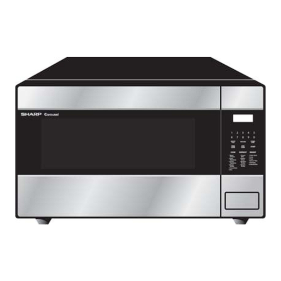
R-409JS
This is a supplemental Service Manual for Microwave Oven model R-409JS. This model is quite similar to the base models
R408JK/JW; (S24M231R408JE).
This supplemental manual must be used in conjunction with the base model service manual for complete operation,
service, safety and replacement parts information.
In the interest of user-safety the oven should be restored to its original condition and only parts identical to those specified
should be used.
WARNING TO SERVICE PERSONNEL: Microwave ovens contain circuitry capable of producing very high voltage and
current, contact with following parts may result in a severe, possibly fatal, electrical shock. (High Voltage Capacitor,
High Voltage Power Transformer, Magnetron, High Voltage Rectifier Assembly, High Voltage Harness etc..)
BEFORE SERVICING ..................................................................................................... INSIDE FRONT COVER
WARNING TO SERVICE PERSONNEL .............................................................................................................. 1
MICROWAVE MEASUREMENT PROCEDURE .................................................................................................. 2
FOREWORD AND WARNING ............................................................................................................................. 3
PRODUCT SPECIFICATIONS ............................................................................................................................. 4
GENERAL INFORMATION ...................................................................................................................................4
KEY UNIT TEST ....................................................................................................................................................6
TOUCH CONTROL PANEL ASSY..................................................................................................................7
CPU UNIT CIRCUIT ............................................................................................................................................. 12
PARTS LIST ........................................................................................................................................................ 13
PACKING AND ACCESSORIES ......................................................................................................................... 17
SHARP ELECTRONCS CORPORATION
Service Headquarters: Sharp Plaza, Mahwah, New Jersey, 07430-2135
MODEL
TABLE OF CONTENTS
This document has been published to be used for after
sales service only.
The contents are subject to change without notice.
S44M236R409JE
MICROWAVE OVEN
R-409JS
R - 4 0 9 J S
Page
Advertisement
Table of Contents

Related Manuals for Sharp R-409JS


Summary of Contents for Sharp R-409JS
-
Page 1: Table Of Contents
MODEL R-409JS This is a supplemental Service Manual for Microwave Oven model R-409JS. This model is quite similar to the base models R408JK/JW; (S24M231R408JE). This supplemental manual must be used in conjunction with the base model service manual for complete operation, service, safety and replacement parts information. -
Page 2: Precautions To Be Observed Before And During Servicing To Avoid Possible Exposure To Excessive Microwave Energy
ELECTRONICS CORPORATION immediately @1-800-237-4277. If the unit operates with the door open, service person should 1) tell the user not to operate the oven and 2) contact SHARP ELECTRONICS CORPORATION and Food and Drug Administration's Center for Devices and Radiological Health immediately. -
Page 3: Warning To Service Personnel
R- 409JS WARNING TO SERVICE PERSONNEL Microwave ovens contain circuitry capable of pro- ducing very high voltage and current, contact with following parts may result in a severe, possibly fatal, electrical shock. (Example) High Voltage Capacitor, High Voltage Power Trans- former, Magnetron, High Voltage Rectifier Assem- bly, High Voltage Harness etc.. -
Page 4: Microwave Measurement Procedure
R - 4 0 9 J S MICROWAVE MEASUREMENT PROCEDURE A. Requirements: 1) Microwave leakage limit (Power density limit): The power density of microwave radiation emitted by a microwave oven should not exceed 1mW/cm at any point 5cm or more from the external surface of the oven, measured prior to acquisition by a purchaser, and thereafter (through the useful life of the oven), 5 mW/cm at any point 5cm or more from the external surface of the oven. -
Page 5: Foreword And Warning
MICROWAVE OVEN R-409JS GENERAL INFORMATION FOREWORD This supplemental Manual has been prepared to provide Sharp Electronics Corp. Service Personnel with Operation and Service Information for the WIRING DIAGRAM SHARP MICROWAVE OVEN, R-409JS. Model R-409JS, is quite similar to base models R-408JK/JW (Ref.# S24M231R408JE). -
Page 6: Product Specifications
R - 4 0 9 J S SPECIFICATION ITEM DESCRIPTION Power Requirements 120 Volts 14.0 Amperes, 1600 watts 60 Hertz Single phase, 3 wire grounded Power Output 1100 watts (IEC TEST PROCEDURE) Operating frequency of 2450MHz Case Dimensions Width 21-21/32" Height 12-3/8"... -
Page 7: Oven Diagram
TOUCH CONTROL PANEL NOTE: The directed features are disa- bled after one minute when the oven is not in use. These features are automatically enabled when the door is opened and closed or the STOP/ CLEAR pad is pressed. R-409JS... -
Page 8: Key Unit Test
R - 4 0 9 J S TEST PROCEDURES PROCEDURE COMPONENT TEST LETTER KEY UNIT TEST 1. Disconnect the power supply cord, and then remove outer case. 2. Open the door and block it open. 3. Discharge high voltage capacitor. 4. -
Page 9: Touch Control Panel Assy
R- 409JS TOUCH CONTROL PANEL ASSEMBLY OUTLINE OF TOUCH CONTROL PANEL 3) Power Source Circuit The touch control section consists of the following units. This circuit generates voltages necessary in the control unit from the AC line voltage. (1) Key Unit In addition, the synchronizing signal is available in order (2) Control Unit (The Control Unit consists of Power Unit and to compose a basic standard time in the clock circuit. - Page 10 R - 4 0 9 J S DESCRIPTION OF LSI The I/O signal of the LSI is detailed in the following table. Pin No. Signal Description VL2-VL1 Power source voltage input terminal. Standard voltage for LCD. AN7-AN4 Terminal to change cooking input according to the Model. By using the A/D converter contained in the LSI, DC voltage in accordance with the Model in operation is applied to set up its cooking constant.
- Page 11 R- 409JS Pin No. Signal Description Signal similar to AN3. When either G11 line on key matrix is touched, a corresponding signal will be input into P41. Connected to GND through the pull-down resistor. RESET Auto clear terminal. Signal is input to reset the LSI to the initial state when power is applied. Signal similar to AN3.
- Page 12 R - 4 0 9 J S Pin No. Signal Description Connected to LCD. The relation between signals are as follows: LSI signal (Pin No.) LCD (Pin No.) LSI signal (Pin No.) LCD (Pin No.) SEG0 (72) ........ SEG 0 SEG11 (61) .......
- Page 13 R- 409JS Installation 1. Remove remaining adhesive on the control panel frame surfaces with a soft cloth soaked in alcohol. 2. Make sure that the LCD sheet and the liquid crystal display is installed in position. 3. Remove the backing paper from the new membrane switch and ribbon cable. 4.
-
Page 14: Cpu Unit Circuit
R - 4 0 9 J S... -
Page 15: Parts List
R- 409JS PARTS LIST Note: The parts marked “∆ ∆ ∆ ∆ ∆ ” may cause undue microwave exposure. The parts marked “*” are used in voltage more than 250V. "§" MARK: PARTS DELIVERY SECTION. REF. NO. PART NO. § DESCRIPTION Q'TY CODE ELECTRIC PARTS... - Page 16 To have your order filled promptly and correctly, please furnish the following information. 1. MODEL NUMBER 2. REF. NO. 3. PART NO. 4. DESCRIPTION Order Parts from the authorized SHARP parts Distributor for your area. Defective parts requiring return should be returned as indicated in the Service Policy.
- Page 17 R- 409JS OVEN AND CABINET PARTS 1-11 4-10 1-10 4-11...
- Page 18 R - 4 0 9 J S CONTROL PANEL PARTS 3-13 3-11 3-10 3-12 DOOR PARTS MISCELLANEOUS Actual wire harness may be different from illustration.
-
Page 19: Packing And Accessories
R- 409JS PACKING AND ACCESSORIES TOP PAD ASSEMBLY DOOR PROTECTION SHEET 6-3 TURNTABLE TRAY PLASTIC BAG TRAY HOLDER 6-6 OPERATION MANUAL BOTTOM PAD ASSEMBLY 6-2 TURNTABLE SUPPORT PACKING CASE... - Page 20 No part of this publication may be repro- duced, stored in retrieval systems, or trans- mitted in any form or by any means, elec- tronic, mechanical, photocopying, recording, or otherwise, without prior written permission of the publisher. 2004 SHARP CORP. (4M2.00E) Printed in U.S.A...
Need help?
Do you have a question about the R-409JS and is the answer not in the manual?
Questions and answers