Table of Contents
Advertisement
CAUTION, MICROWAVE RADIATION ............................................................................................................. 1
WARNING .......................................................................................................................................................... 1
PRODUCT SPECIFICATIONS ......................................................................................................................... 2
GENERAL INFORMATION ................................................................................................................................ 2
APPEARANCE VIEW ....................................................................................................................................... 3
OPERATION SEQUENCE ................................................................................................................................ 4
FUNCTION OF IMPORTANT COMPONENTS ................................................................................................ 5
SERVICING ...................................................................................................................................................... 6
TEST PROCEDURE ......................................................................................................................................... 8
TOUCH CONTROL PANEL ............................................................................................................................. 14
COMPONENT REPLACEMENT AND ADJUSTMENT PROCEDURE ........................................................... 18
MICROWAVE MEASUREMENT .................................................................................................................... 24
WIRING DIAGRAM ......................................................................................................................................... 25
PICTORIAL DIAGRAM ................................................................................................................................... 26
POWER UNIT CIRCUIT .................................................................................................................................. 27
CPU UNIT CIRCUIT ........................................................................................................................................ 30
PRINTED WIRING BOARD ............................................................................................................................. 30
PARTS LIST ................................................................................................................................................... 32
SERVICE MANUAL
SENSOR DEFROST
COOK
HELP
HELP
PASTA MEAL
FROZEN DINNER
DINNER
CASSERO LE
PLATE
SOUP
PIZZA
BEVERA GE
PIE
VEGET ABLES
RICE/P ASTA
MEAT
EASY DEFRO ST
LESS
MORE
1
2
3
4
5
6
7
8
9
0
POW ER
LEVE L
CLOC K
TIME R
STOP
INSTA NT COOK
CLEA R
STAR T
In interests of user-safety the oven should be restored to its original
condition and only parts identical to those specified should be used.
TABLE OF CONTENTS
SHARP CORPORATION
MICROWAVE OVEN
R-450C
MODEL
R-450C
S7906R450CPJ/
Page
Advertisement
Table of Contents

Related Manuals for Sharp R-450C


Summary of Contents for Sharp R-450C
-
Page 1: Table Of Contents
R-450C SERVICE MANUAL S7906R450CPJ/ MICROWAVE OVEN SENSOR DEFROST COOK HELP HELP R-450C PASTA MEAL FROZEN DINNER MODEL DINNER CASSERO LE PLATE SOUP PIZZA BEVERA GE VEGET ABLES RICE/P ASTA MEAT EASY DEFRO ST LESS MORE POW ER LEVE L CLOC K... - Page 2 R-450C...
-
Page 3: Caution Microwave Radiation
MICROWAVE OVEN APPEARANCE VIEW R-450C GENERAL IMPORTANT INFORMATION This Manual has been prepared to provide Sharp Corp. Service OPERATING SEQUENCE engineers with Operation and Service Information. It is recommended that service engineers carefully study the entire text of this manual, so they will be qualified to render FUNCTION OF IMPORTANT satisfactory customer service. -
Page 4: Product Specifications
R-450C PRODUCT SPECIFICATIONS ITEM DESCRIPTION Power Requirements 230 - 240 Volts 50 Hertz Single phase, 3 wire earthed Power Consumption 1.6 kW Power Output 1100 watts nominal of RF microwave energy (IEC 705) Operating frequency 2450 MHz Case Dimensions Width 550 mm... -
Page 5: Appearance View
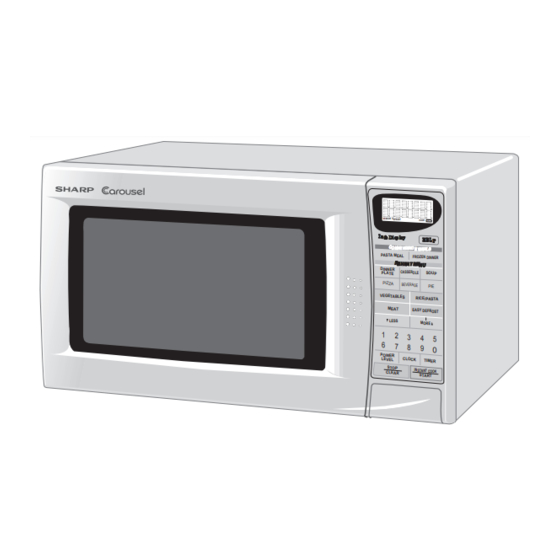
R-450C APPEARANCE VIEW 1. Ventilation openings 2. Oven lamp 3. Door hinges 4. Door safety latches 5. See through door 6. Door seals and sealing surfaces 7. Coupling 8. Door open button 9. Touch control panel 10.Digital readout 11.Waveguide cover 12.Power supply cord... -
Page 6: Operation Sequence
Figure O-1 on page 25 latch switch and stop switch must open their contacts 1. The display shows SHARP, MICRO-WAVE and OVEN. first. After that the contacts (COM-NC) of the monitor 2. To set any programs or set the clock, you must first switch can be closed. -
Page 7: Function Of Important Components
R-450C FUNCTION OF IMPORTANT COMPONENTS DOOR OPEN MECHANISM will open at 145˚C, causing the oven to shut down. The defective thermal cut-out must be replaced with new one. The door can be opened by pushing the door open button on the control panel. When the door open button is... -
Page 8: Servicing
Sharp recommend that wherever possible fault-finding is carried out with the supply disconnected. It may in, some cases, be necessary to connect the supply after... - Page 9 R-450C CK = Check / RE = Replace TEST PROCEDURE A B C D E E E E F G H H I I J K L M N O RE RE CK CK CK CK CK CK CK CK...
-
Page 10: Test Procedure
R-450C TEST PROCEDURES PROCEDURE COMPONENT TEST LETTER MAGNETRON TEST NEVER TOUCH ANY PART IN THE CIRCUIT WITH YOUR HAND OR AN INSULATED TOOL WHILE THE OVEN IS IN OPERATION. CARRY OUT 3D CHECKS. Isolate the magnetron from high voltage circuit by removing all leads connected to filament terminal. - Page 11 R-450C TEST PROCEDURES PROCEDURE COMPONENT TEST LETTER Initial temperature ....................T1 = 11°C Temperature after (38 + 2) = 40sec..............T2 = 21°C Temperature difference Cold-Warm ..............∆T1 = 10°C Measured output power The equation is “P = 110 x ∆T” ..........P = 110 x 10°C = 1100 Watts JUDGMENT: The measured output power should be at least ±...
- Page 12 R-450C TEST PROCEDURES PROCEDURE COMPONENT TEST LETTER HIGH VOLTAGE CAPACITOR TEST CARRY OUT 3D CHECKS. A. Isolate the high voltage capacitor from the circuit. B. Continuity check must be carried out with measuring instrument which is set to the highest resistance range.
- Page 13 R-450C TEST PROCEDURES PROCEDURE COMPONENT TEST LETTER CARRY OUT 4R CHECKS. Table: Thermal cut-out Test Temperature of "ON" Temperature of "OFF" Indication of ohmmeter Parts Name condition (closed circuit) (˚C) condition (open circuit) (˚C) (When room temperature is approx. 20˚C) Thermal cut-out 145˚C...
- Page 14 R-450C TEST PROCEDURES PROCEDURE COMPONENT TEST LETTER units, Control Unit and Key Unit, and also the Control Unit is divided into two units, CPU Unit and Power Unit, and troubleshooting by unit replacement is described according to the symptoms indicated.
- Page 15 R-450C TEST PROCEDURES PROCEDURE COMPONENT TEST LETTER RELAY TEST Remove the outer case and check voltage between Pin No 1 of the 2-pin connector (A) and the common terminal of the relay RY1 on the power unit with an A.C. voltmeter. The meter should indicate 230 - 240 volts, if not check oven circuit.
-
Page 16: Touch Control Panel
R-450C TOUCH CONTROL PANEL ASSEMBLY OUTLINE OF TOUCH CONTROL PANEL The touch control section consists of the following units. 3) Power Source Circuit This circuit generates voltages necessary in the con- (1) Key Unit trol unit from the AC line voltage. - Page 17 R-450C LSI(IZA969DR) The I/O signal of the LSI(IZA969DR) is detailed in the following table. Pin No. Signal Description AN10 Signal coming from touch key. When either G10 line on key matrix is touched, a corresponding signal out of P10 - P17 will be input into AN10.
- Page 18 R-450C Pin No. Signal Description Oven lamp, fan motor and turntable motor driving signal 20.0 msec. To turn on and off shut off relay (RY1). The H : GND square waveform voltage is delivered to the RY1 driving circuit and RY2 control circuit.
- Page 19 R-450C TOUCH CONTROL PANEL SERVICING 1. Precautions for Handling Electronic Components both ends of the door sensing switch (on PWB) of the This unit uses CMOS LSI in the integral part of the touch control panel with a jumper, which brings about circuits.
-
Page 20: Component Replacement And Adjustment Procedure
WARNING FOR WIRING and Oven cavity. To prevent an electric shock, take the following manners. 3) Sharp edge: Bottom plate, Oven cavity, Waveguide flange, 1. Before wiring, Chassis support and other metallic plate. 1) Disconnect the power supply. -
Page 21: Pictorial Diagram
4. Where the portions have been snipped off bend portions plate left near by the turntable motor cover. This screw flat. No sharp edge must be evident after removal of the will be used at the following step 3. turntable motor cover. -
Page 22: Control Panel Assembly Removal
R-450C OVEN LAMP AND LAMP SOCKET REMOVAL 9. Now, the oven lamp and lamp socket are free. 1. CARRY OUT 3D CHECKS. 2. Remove one (1) screw holding the chassis support to the magnetron and magnetron air duct. Oven lamp socket 3. -
Page 23: Power Supply Cord Replacement
R-450C 2. Install the fan motor to the back plate of the oven cavity 4. Connect the wire leads to the fan motor and magnetron, with the two (2) screws. referring to the pictorial diagram. 3. Re-install the fan duct to the oven cavity. -
Page 24: Door Replacement
R-450C toward the oven face. Then check lower portion of the Door latch hook, pushing and pulling lower portion of the Latch Hook door toward the oven face. Both results (play in the door) should be less than 0.5mm. Latch 2. - Page 25 R-450C 6. Re-install the latch spring to the latch head. Re-install the latch spring to the door frame. Re-install latch head Upper oven hinge to door frame. 7. Re-install choke cover to door panel by pushing. 8. Catch two (2) pins of door panel on two (2) hole of upper Door and lower oven hinges as shown Figure C-7.
- Page 26 R-450C MICROWAVE MEASUREMENT Recommended instruments are: After adjustment of door latch switches, monitor switch NARDA 8100 and door are completed individually or collectively, the NARDA 8200 following leakage test must be performed with a survey HOLADAY HI 1500 instrument and it must be confirmed that the result meets...
- Page 27 R-450C SCHEMATIC NOTE: CONDITION OF OVEN 1. DOOR CLOSED. 2. CLOCK APPEARS ON DISPLAY. NOTE: " " indicates components with potentials above 250V. MAGNETRON TEMPERATURE 2ND. LATCH FUSE SWITCH FUSE M10A COM. COM. N.O. N.O. RY-1 RY-2 H. V. FUSE CONTROL 0.75A...
- Page 28 R-450C...
- Page 29 R-450C CN-C 12PIN LEAD WIRE HARNESS Q2 2SB1238 R4 27 R5 4.7k D1-D4 11ES1 CN-A 1SS270A 1SS270A – – R2 510 1w R3 390 1/2w SP1 PKM22EPT OVEN LAMP TURNTABLE MOTOR FAN MOTOR Q3 KRC243M BUZZER R6 3.3k OVEN LAMP...
- Page 30 R-450C SEG6 SEG7 SEG8 SEG9 SEG10 SEG11 SEG12 SEG13 SEG14 SEG15 SEG16 SEG17 SEG18 SEG19 TEST SEG20 OSC1 OSC2 AVSS AN11 SEG35 AN10 4.7k C110 4.7k 4.7k 330pF/50v (J16) (J17) 330pF/50v 4.7k 330pF/50v (J14) (J15) 330pF/50v 4.7k 330pF/50v (J12) (J13) 330pF/50v 4.7k...
- Page 31 R-450C DEFROST COOK HELP SEG9 SEG35 SEG8 SEG36 SEG7 SEG37 SEG6 SEG38 SEG5 SEG39 SEG4 COM16 SEG3 COM15 0.1µ/50v SEG2 COM14 SEG1 COM13 C129 SEG0 COM12 COM7 COM11 COM6 COM10 COM5 COM9 COM4 COM8 COM3 COM2 COM1 COM0 OSC1 OSC2...
-
Page 32: Printed Wiring Board
R-450C (CN - C) CN - C CN - B CN - A (CN - D) (D10) Figure S-5. Printed Wiring Board PARTS LIST Note: The parts marked " ∆ " may cause undue microwave exposure. The parts marked "*" are used in voltage more than 250V. - Page 33 R-450C Note: The parts marked " ∆ " may cause undue microwave exposure. The parts marked "*" are used in voltage more than 250V. REF. NO. PART NO. DESCRIPTION Q'TY CODE 1- 6 QACCAA047WRE0 Power supply cord 1- 7 FH-DZA069WRK0 H.V.
- Page 34 R-450C Note: The parts marked " ∆ " may cause undue microwave exposure. The parts marked "*" are used in voltage more than 250V. REF. NO. PART NO. DESCRIPTION Q'TY CODE 4-19 PCUSUA237WRP0 Cushion 4-20 PSKR-A319WRF0 MG air guide 4-21...
-
Page 35: Oven And Cabinet Parts
R-450C OVEN AND CABINET PARTS 4-14 4-11 1-10 4-22 4-21 1-15 4-15 4-19 4-13 1-13 1-11 1-12 1-14 4-16 1-16 4-17 4-12 4-23 4-20 1-17 4-10... - Page 36 R-450C CONTROL PANEL PARTS DOOR PARTS 3-3-1 4-18 3-3-3 3-3-2 MISCELLANEOUS Actual wire harness may be different from illustration. '99SHARP CORP. (07S0.720E) Printed in Australia...
Need help?
Do you have a question about the R-450C and is the answer not in the manual?
Questions and answers