Advertisement
INDEX
Page
Contents
2
3
4
5
7
14
20
20
21
SHARPY WASH 33
INSTRUCTION MANUAL
Congratulations on choosing a Clay Paky product
We thank you for your custom.
Please note that this product, as all the others in the rich Clay
Paky range, has been designed and made with total quality to
ensure excellent performance and best meet your expectations
and requirements.
Carefully read this instruction manual in its entirety and keep it
safe for future reference. It is essential to know the information
and comply with the instructions given in this manual to ensure
the fitting is installed, used and serviced correctly and safely.
CLAY PAKY S.p.A. disclaims all liability for damage to the fitting
or to other property or persons deriving from installation, use and
maintenance that have not been carried out in conformity with this
instruction manual, which must always accompany the fitting.
CLAY PAKY S.p.A. reserves the right to modify the
characteristics stated in this instruction manual at any time and
without prior notice.
1
C61378
Advertisement
Table of Contents

Related Manuals for Clay Paky SHARPY WASH 330


Summary of Contents for Clay Paky SHARPY WASH 330
-
Page 1: Table Of Contents
Menu setting CLAY PAKY S.p.A. disclaims all liability for damage to the fitting or to other property or persons deriving from installation, use and Maintenance maintenance that have not been carried out in conformity with this instruction manual, which must always accompany the fitting. -
Page 2: Safety Information
SAFETY INFORMATION • Installation Make sure all parts for fixing the projector are in a good state of repair. Make sure the point of anchorage is stable before positioning the projector. The safety chain must be properly hooked onto the fitting and secured to the framework, so that, if the primary support system fails, the fitting falls as little as possible. -
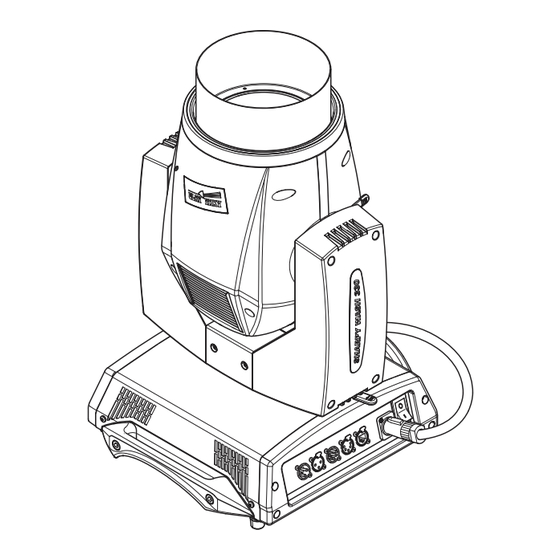
Page 3: Unpacking And Preparation
UNPACKING AND PREPARATION IST001/001 2 x 183102/802 Lamp 330W (fitted into projector) Packing contents - Fig. 1 LOCKED UNLOCKED PAN Mechanism Lock and Release (every 90°) - Fig. 2 TILT Mechanism Lock and Release (every 45°) - Fig. 3 SHARPY WASH 33... -
Page 4: Installation And Start-Up
INSTALLATION AND START-UP Installing the projector - Fig. 4 The projector can be installed on the floor resting on special rubber feet, on a truss or on the ceiling or wall. WARNING: with the exception of when the projector is positioned on the floor, the safety cable must be fitted. (Cod. 105041/003 available on request). This must be securely fixed to the support structure of the projector and then connected to the fixing point at the centre of the base. -
Page 5: Control Panel
CONTROL PANEL Mains Connecting to the mains supply - Fig. 6 Connecting to the control signal line (DMX) - Fig. 7 Use a cable conforming to specifications EIA RS-485: 2-pole twisted, shielded, 120Ohm characteristic impedance, 22-24 AWG, low capacity. Do not use microphone cable or other cable with characteristics differing from those specified. - Page 6 Reversal of the display - Fig. 9 To activate this function, press UP and DOWN keys simultaneously while the display is in the rest mode. This status will be memorised and maintained even for the next time it will be switched on. To return to the initial state, repeat the operation all over again. Setting the projector starting address On each projector, the starting address must be set for the control signal (addresses from 1 to 512).
-
Page 7: Menu Setting
MENU SETTING System Set Up Option Lamp Dmx Information Address Errors Channel Fixture Invert Pan / Tilt Mode Hours Invert Lamp Fixture ID Tilt Hours Swap Pan-Tilt Ethernet Lamp Interface Strikes Encoder Pan-Tilt System Option Version Color Color Mixing Board Information Fixed Wheel Diagnostic... -
Page 8: Set Up Menu
NOTE: On grey the default options SET UP MENU DMX ADDRESS Set Up Address xxx NOTE: without the DMX signal the Address (XXX) flashing Address Allows you to select the DMX ADDRESS. 1) Press - the current DMX Adress appear on the display. 2) Use the UP and DOWN , RIGHT... -
Page 9: Options Menu
OPTIONS MENU LAMP DMX Option Lamp Dmx Used for enabling lamp remote control channel. 1) Press - the current settings appear on the display (On or Off). 2) Use the UP and DOWN keys to enable (On) or disable (Off) the lamp remote control channel. - Page 10 SHUTTER Shutter Shutter Shutter on error On Error Used for automatically closing the stop/strobe in the event of Pan/Tilt position error. 1) Press - the current settings appear on the display (On or Off). 2) Use the UP and DOWN keys to enable (On) or disable (Off) automatic stop/strobe closing in the event of Pan/Tilt position error.
- Page 11 System INFORMATION MENU Information Errors SYSTEM ERRORS Shows a list of warnings and messages relevant to errors occurred since the fixtures switching-on. 1) Pressing you are allowed to reset the SYSTEM ERRORS list. A confirmation message (Are you sure you want to clear error list ?) appears on the display.
- Page 12 DMX MONITOR Monitor Used for displaying the projector DMX channel level in bit (Val) and in percentage (Perc). FANS MONITOR Fans Speed (RPM) Monitor Lamp XXXX Used for displaying the speed of each fan installed in the projector: Lamp XXXX Lamp (Lamp Fan) BallIn XXXX...
-
Page 13: Advanced Menu
ADVANCED MENU To enable the Advanced Menu set up the Access code (1234) using the Code Advanced , DOWN , RIGHT keys. 1234 Press - Menu advanced appears on the display UP LOAD FIRMWARE Transfer the firmware on all the connected fixtures ? Upload Allows you to transfer the firmware from 1 fixture to all the connected fixtures. -
Page 14: Maintenance
MAINTENANCE 1/4 Turn 1/4 Turn Locking and releasing Pan and Tilt movements - Refer to the instructions in the UNPACKING AND PREPARATION section. Opening the head covers - Fig. 10. Closing the head covers - Fig. 11. SHARPY WASH 33... - Page 15 Upper Side 1/4 Turn tooltip Lamp change - Fig 12, 13, 14, 15. Take the new lamp out of its package and insert in the fitting. WARNING: do not touch the lamp s envelope with bare hands. Should this happen, clean the bulb with a cloth soaked in alcohol and dry it with a clean, dry cloth.
- Page 16 • General cleaning of internal parts. • Restoring lubrication of all parts subject to friction, using lubricants specifically supplied by Clay Paky. • General visual check of the internal components, cabling, mechanical parts, etc.
- Page 17 Lower Side Extraction of the effect modules: Preliminary operations - Fig. 17 Continue SHARPY WASH 33...
- Page 18 Upper Side Upper Side Upper Side Upper Side Extraction of the effect modules - Fig. 18 IMPORTANT: Grasp the modules using the support structure and not the details which could get damaged. Insertion of the effect modules: Repeat the operations indicated in Fig. 17 and 18 in reverse order. SHARPY WASH 33...
- Page 19 Battery removal - Fig. 19 This product contains a rechargeable lead-acid or lithium iron tetraphosphate battery. To preserve the environment, please dispose the battery at the end of its life according to the regulation in force. LiFePO4 SHARPY WASH 33...
-
Page 20: Technical Information
TECHNICAL INFORMATION (19.29") Top Hat OUT Power supplies available IP20 protection rating: 115/230V 50/60Hz • Protected against the entry of solid bodies larger (15.35") than 12mm (0.47”). Top Hat IN Input power: • No protection against the entry of liquids. 520VA a 230V 50Hz. -
Page 21: Channel Functions
CHANNEL FUNCTION NB: To prevent accidental breakage of the effects, which could collide with each other during transport, SHARPY WASH 330 before switching the projector OFF check that all the projector Channels have been excluded (DMX level = 0%). DMX Modality... - Page 22 NOTE: On conclusion of resetting in case of absence of DMX signal, Pan & Tilt move to the Home position (Pan 50% - Tilt 50%) all the others channels stay at 0%. • COLOUR MIXING - channel 1 - 2 - 3 •...
- Page 23 • BEAM SHAPER ROTATION - channel 9 • PAN - channel 13 Operation with option InvertPan EFFECT (Tilt conventionally represented at 14% and option Invert Tilt Off) FAST ROTATION (43 rpm) SLOW ROTATION (1.1 rph) STOP 191 - 192 STOP SLOW ROTATION (1.1 rph) FAST ROTATION (43 rpm) POSITION 540°...
- Page 24 • FUNCTION - channel: 17 • TILT - channel 15 Operation with option Invert Tilt EFFECT (Pan conventionally represented at 0% and option Invert Pan Off) UNUSED RANGE 76-87 CMY Limited range CMY CURVE FUCTION 63-75 CMY Full range (Default) 51-62 LINEAR (Default) DIMMER CURVE...
- Page 25 TIMING CHANNELS Timing Channel Channel function Pan - Tilt time Pan - Tilt - (Pan fine - Tilt fine) Colour time Colour wheel - CTO Beam time Dimmer - Frost TIME TABLE Seconds Seconds Seconds Seconds Seconds Seconds Full 10.2 10.4 10.6 Follow cue...
- Page 28 CLAY PAKY - Via Pastrengo, 3/b - 24068 Seriate (BG) Italy - Tel. +39-035-654311 - Fax +39-035-301876 - www.claypaky.it S.p.A.
Need help?
Do you have a question about the SHARPY WASH 330 and is the answer not in the manual?
Questions and answers