Garmin GNS 430 Pilot Operating Handbook
Hide thumbs
Also See for GNS 430:
- Pilot's manual & reference (267 pages) ,
- Pilot's manual and reference (234 pages) ,
- Operating manual (27 pages)
Table of Contents
Advertisement
Quick Links
Cirrus Design
SR20
FAA Approved Airplane Flight Manual
Garmin GNS 430 GPS Navigator
When a Garmin GNS 430 GPS Navigator with NAV, ILS, and COM is
installed in the Cirrus Design SR20 this Supplement is applicable and
must be inserted in the Supplements Section (Section 9) of the Cirrus
Design SR20 Pilot's Operating Handbook. This document must be
carried in the airplane at all times. Information in this supplement
either adds to, supersedes, or deletes information in the basic SR20
Pilot's Operating Handbook.
This POH Supplement Revision dated Revision 2: 08-15-07
supersedes and replaces the Revision 1 of this supplement
dated 05-25-05.
Serials 1005 thru 1267; This supplement replaces GNS 430
GPS Navigator supplement. P/N 11934-S03 original release
or later.
P/N 11934-S22
Revision 2: 08-15-07
Pilot's Operating Handbook and
Supplement
• Note •
For
Section 9
Supplements
1 of 10
Advertisement
Table of Contents

Related Manuals for Garmin GNS 430


Summary of Contents for Garmin GNS 430
- Page 1 Supplement Garmin GNS 430 GPS Navigator When a Garmin GNS 430 GPS Navigator with NAV, ILS, and COM is installed in the Cirrus Design SR20 this Supplement is applicable and must be inserted in the Supplements Section (Section 9) of the Cirrus Design SR20 Pilot’s Operating Handbook.
- Page 2 SR20 Section 1 - General The airplane is equipped with a Garmin GNS 430 GPS Navigator with VHF Nav, ILS, and VHF Com herein referred to as the “Navigator.” The GNS 430 is capable of providing IFR enroute, terminal, and approach navigation with position accuracies better than 15 meters.
- Page 3 Navigation data is based upon use of only the global positioning system (GPS) operated by the United States. 2. The Garmin GNS 430 Pilot's Guide and Reference, P/N 190- 00140-00, Revision F dated July 2000 (or later appropriate revision) must be immediately available to the flight crew whenever navigation is predicated on the use of the GPS Navigator.
-
Page 4: Section 3 - Emergency Procedures
IFR approved navigation system. Section 4 - Normal Procedures The GARMIN GNS 430 Navigator is available in single or dual installations. Operating procedures for each unit of a dual installation are identical. Refer to the GNS 430 Integration paragraphs in this supplement for integration differences when single and dual units are installed. - Page 5 The GNS 430 Navigator is integrated into the SR20 Avionics installation in three configurations: 1. Single GARMIN GNS 430 (GPS 1) interfaced with the CDI and MFD and a single GARMIN GNC 250XL (GPS 2) not integrated with a remote indicator.
- Page 6 Cirrus Design Supplements SR20 2. Single GARMIN GNS 430 (GPS 1) interfaced with the HSI and MFD and a single GARMIN GNC 420 (GPS 2) interfaced with the CDI (VOR/LOC) indicator. a. In this configuration, pressing the alternate-action CDI push-...
- Page 7 The following paragraphs describe a single GARMIN GNS 430 unit and its functions. In the event a second GNS 430 is installed, the second unit will function as described below except that the GPS navigator is designated GPS 2, the NAV receiver is designated NAV 2, and the VHF communications receiver is designated COM 2.
-
Page 8: Gps Navigator
Normally, the second GPS Navigator provides backup and is approved for VFR use only. If the second GPS is also a Garmin 430, it will be coupled to the CDI and is also approved for IFR use. The Garmin GPS 430 is capable of providing IFR enroute, terminal, and approach navigation with position accuracies better than 15 meters. -
Page 9: Navigation (Nav) Receiver
Section 9 SR20 Supplements Jeppesen NavData card slot in each panel. The GNS 430 navigator is powered by 28 VDC through the 5-amp GPS1 circuit breaker on the Avionics Essential Bus. The Jeppesen Navigation Database provides access to data on... -
Page 10: Terrain Interface
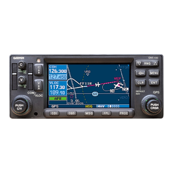
Cirrus Design Supplements SR20 side of the GNS 430 front panel. Frequency tuning is accomplished by rotating the large and small concentric knobs to select a standby frequency and then transferring the frequency to the active window. The COM frequency display window is at the upper left corner of the GNS 430 display.
Need help?
Do you have a question about the GNS 430 and is the answer not in the manual?
Questions and answers