Table of Contents

Related Manuals for Ness EDR1600


Summary of Contents for Ness EDR1600
- Page 1 EDR1600 1 6 C H A N N E L D I G I TA L V I D E O R E C O R D E R I N S T R U C T I O N M A N U A L Before installing and using this unit, please read this manual carefully.
- Page 2 WARNING TO REDUCE RISK OF FIRE OR ELECTRIC SHOCK, DO NOT EXPOSE THIS APPLIANCE TO RAIN OR MOISTURE. CAUTION DO NOT REMOVE COVER. NO USER SERVICEABLE PARTS INSIDE. REFER SERVICING TO QUALIFIED SERVICE PERSONNEL. WARNING: This equipment has been tested and found to comply with the limits for a Class “A”...
- Page 3 Administrator’s Guide and Operating Instructions PRECAUTIONS Refer all work related to the installation of this product to qualified service personnel or system installers. Do not block the ventilation opening or slots on the cover. Do not drop metallic parts through slots. This could permanently damage the appliance.
-
Page 4: Table Of Contents
Table of Contents 1. Product Overview………………….……………………….……... 1.1 Features…………………..……….…………..…………………... 1.2 Technical Overview…….….…….………………………….…….. 2. Front & Rear Panels….…….……………………………….……. 3. System Installation…….…….……………………………….…… 3.1 Before Installation…….……….…………………………….……. 3.2 Basic Connections…………….…………………………….…….. 3.3 Optional Connections…………..…………………………….…… 4. Main Screen…………………………………………..……….…... 5. Basic Operations & Log Display……………………..………..…. 5.1 Version Display……………………………..…………….…….… 5.2 Alarm Message Display……………………...……………………... -
Page 5: Product Overview
1. Product Overview The PowerPlex EDR1600 is a state-of-the-art digital video recorder that brings unparalleled price/performance video surveillance, recording and playback to the CCTV systems. With parallel processing architecture, high performance video engine, and intelligent recording algorithms, triplex operation can be easily achieved without sacrificing the increasing demands of performance, reliability, and availability in the CCTV industry. -
Page 6: Technical Overview
1.2 Technical Overview 1.2.1 Video Input and Output The digital video recorder is designed to support either NTSC/EIA or PAL/CCIR standard. To make the auto detection of video standard work, at least one camera must be connected to the video input. The product features video camera inputs with a passive looping output for each. - Page 7 disk, ZIP disk, etc. in .MPG format for MPEG-1 encoded video or .MOV format for JPEG encoded video. For Time-Lapse Mode Recording Time, please refer to Appendix B. 1.2.4 Motion Detection The digital video recorder continuously monitors all camera inputs for motion.
- Page 8 RAID (Redundant Arrays of Independent Disks) or SCSI disks, which are very expensive. With the Expandable IDE Hard Disk Architecture, the EDR1600 can support up to 18 pieces of IDE hard disks that are hot swappable. With 40 GB of storage per hard disk, the system storage is more than 700 GB and virtually unlimited –...
-
Page 9: Front & Rear Panels
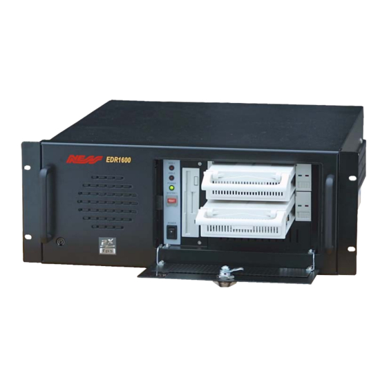
2. Front & Rear Panels The following is a brief overview of the front panel and rear panel of EDR1600. 0. Power Switch From Rear Panel 1. Power Selector Switch: 115V AC or 230V AC selector switch. Warning: To avoid damaging the system, set this switch before plugging in the power plug. - Page 10 Administrator’s Guide and Operating Instructions 5. USB Connector: Reserved. 6. RS-232 Connector: Com 1, connects to modem. 7. Printer Port Connector: Connects to printer port devices (e.g. ZIP/printer port). 8. RS-232 Connector: Com 2, connects to PTZ camera. 9. External Hard Disk Connector: Connects to External Hard Disk Array EDA800.
-
Page 11: Front Panel
Administrator’s Guide and Operating Instructions Front Panel 25. Hard Disk Trays: Hard disk holders for HDD#1 (upper tray) and HDD#2 (lower tray). Note: Please make sure to set HDD#1 as master and HDD#2 as slave. The settings should be described on the hard disk itself or in the manual come with the hard disk. -
Page 12: System Installation
3.1 Before Installation Please make sure to set the Power Selector Switch before plugging in the power plug to avoid damaging the EDR1600. Use a screwdriver to set the switch to the correct position so that the number shown is the same as the local AC voltage. -
Page 13: Basic Connections
3.2 Basic Connections Cameras Connect each of the camera video input connector to the video output from a camera or other composite video source. At least one camera must be connected before the system is running for the auto detection of video standard to take effect. VGA Monitor Connect the VGA monitor output connector to a VGA monitor. - Page 14 EDA800 Connect the External Hard Disk Connector to EDA800 if the user has purchased EDA800. If EDR1600 is running, please power on EDA800 first, and then make the connection. Main TV Monitor Connect the Main Monitor Output Connector to a TV monitor. This monitor displays selected live or recorded cameras in any available format.
-
Page 15: Main Screen
4. Main Screen The diagram above is the main screen display. The icons on the lower corner of the screen are mainly for control and configuration, those on the right corner for status indication. If any icon is grayed, it means that the specific function is not accessible in the current mode or login right. - Page 16 Administrator’s Guide and Operating Instructions Alarm Event Log – To view the event log. Config – To configure (setup) the behaviors of the system. TV Overscan/Underscan – To change the display size of the Main TV Monitor. Login – To login the system as Administrator, Supervisor or Operator.
-
Page 17: Basic Operations & Log Display
Administrator’s Guide and Operating Instructions There are 4 kinds of devices in the status indication. The displaying order is Camera, Alarm Output, Hard Disk, Alarm Input, then back to Camera. Each status bar stands for the status of one device, the bottommost for ID#1. -
Page 18: Version Display
There are 4 kinds of event logs: Alarm, Motion, Video Loss, and Power On/Off. To view the event Log display, please click on the Log icon. The screen will be shown as below: If you logged in as Administrator, the Delete button and Delete All button will be enabled. -
Page 19: Setup (Administrator)
6. Setup (Administrator) To login as an Administrator, please click on the Login icon, and enter the appropriate Administrator’s Login name and Password (the factory default value for both of them is admin). To setup the behaviors of the system, please click on the Config icon. The configuration menu will pop up as below. -
Page 20: Time Type Setup
6.1 Time Type Setup The behavior for the system is the same when it’s in the same time Type (or Time Mode). Please refer to Camera Setup and Motion Setup for how they depend on Time Type. There are 2 default Time Types, On duty and Off duty, in the system. -
Page 21: Day Type Setup
6.2 Day Type Setup The daily behaviors for the system are the same for those days configured as of the same Day Type. There are 2 default Day Types, WORK DAY (Monday through Friday) and HOLIDAY (Saturday and Sunday), in the system. However, you may configure up to 16 Day Types to suit your needs. -
Page 22: Calendar Setup
Administrator’s Guide and Operating Instructions 6.3 Calendar Setup The Calendar setup is provided for the administrator to set the Day Type of each calendar day. It’s designed to be a Perpetual Calendar. However, up to 10 years of calendar days can be configured at any specific time. -
Page 23: Alarm Action Setup
6.4 Alarm Action Setup The Alarm Actions allow the administrator to define how the digital video recorder responds to the triggered alarm from the Alarm Inputs. There are up to 16 Alarm Actions that correspond to 16 (Focus) Cameras for most applications. For each Alarm Action, you may configure its behaviors as shown on the screen and described below. - Page 24 Focus Camera – To define the camera that will respond to this Alarm Action. The default settings are Camera 1 for Alarm Action 1, Camera 2 for Alarm Action 2, and so on. Pre-record – Pre-record time to define how long (in seconds) before the Alarm Action is triggered the Focus Camera shall be intensively recorded (Note 2).
- Page 25 Administrator’s Guide and Operating Instructions Call Display – If it is checked, the Call Monitor will switch to the Focus Camera when the Alarm Action is triggered. Otherwise, the Call Monitor will switch among all the installed cameras as usual. Log –...
-
Page 26: Motion Action Setup
6.5 Motion Action Setup The Motion Actions allow the administrator to define how the digital video recorder responds to the detected motion for the cameras. There are up to 8 Motion Actions that correspond to 8 Alarm Outputs for most applications. The Focus Camera is always the camera with the detected motion. -
Page 27: Video Loss Action Setup
6.6 Video Loss Action Setup The Video Loss Actions allow the administrator to define how the digital video recorder responds to the detected video loss for the cameras. There are up to 8 Video Loss Actions that correspond to 8 Alarm Outputs for most applications. -
Page 28: Hard Disks Full Action Setup
6.7 Hard Disks Full Action Setup The Hard Disks Full Actions allow the administrator to define how the digital video recorder responds when the hard disk drives reach the maximum storage capacity. Operations: After the HDDs Full Action menu item is selected, the HDDs Full Action Setup dialog box will be shown on the screen. - Page 29 Alarm Out – To define which Alarm Output will be triggered when the hard disk capacity is full. NC and NO signals are available, please refer to Alarm Out Setup. Click on the Down arrow button to select one of the Alarm Outputs (AO 1-8). Output –...
-
Page 30: Camera Setup
6.8 Camera Setup The Camera Setup allows the administrator to define the behaviors for each Camera at each Time Type. There are up to 16 Cameras connected to the system. For each Camera and each Time Type, you may configure the behaviors as shown on the screen and described below. - Page 31 Recording Quality For All Cameras – The range is 0-10, with 0 the lowest (rough) quality, 10 the highest (fine) quality. The default value is 5 . Use the Up/Down arrow buttons to adjust the value. Compression Method For All Cameras – MPEG (MPEG-1) or JPEG-CIF (JPEG), resolution –...
-
Page 32: Alarm In Setup
6.9 Alarm In Setup The Alarm In Setup allows the administrator to define the behaviors for each Alarm Input at each Time Type. There are up to 24 Alarm Inputs connected to the system. For each Alarm Input and each Time Type, you may enable/disable and select its corresponding Alarm Action. - Page 33 Administrator’s Guide and Operating Instructions Normal State – NC or NO, please check the signal types connected to the Alarm Input Terminal on the rear panel of the system. Use the Down arrow button to select the signal type. Enable Alarm Action – Check to Enable Alarm Action for the selected Alarm Input at the selected Time Type.
-
Page 34: Alarm Out Setup
6.10 Alarm Out Setup The Alarm Out Setup allows the administrator to define the tag name for each Alarm Output. There are up to 4 Normally Closed (NC) signals (AO 1-4) and 4 Normally Open (NO) signals (AO 5-8) for the system. -
Page 35: Display Sequence Setup
6.11 Display Sequence Setup The Display Sequence Setup allows the administrator to define the Sequence Mode display. Please refer to Chapter 4 for Sequence Mode display. For the definition of the Display Pages in each Display Sequence, please refer to Display Page Setup. Operations: After the Display Seqs menu item is selected, the Display Sequence Setup dialog box will be shown on the screen. -
Page 36: Display
6.12 Display Page Setup The Display Page Setup allows the administrator to define the Display Pages in Sequence Mode display and Static Page Mode display (please refer to Chapter 4). Operations: After the Display Pages menu item is selected, the Display Page Setup dialog box will be shown on the screen. - Page 37 Administrator’s Guide and Operating Instructions Static Page Mode – To set the Display Pages for Static Page Mode display. Sequence No – To select the Sequence Number in Sequence Mode display. Use the Down arrow button to select the number. Page No - To select the Page Number for the selected Sequence Number in Sequence Mode display.
-
Page 38: Motion Setup
Administrator’s Guide and Operating Instructions 6.13 Motion Setup The Motion Setup allows the administrator to configure how motion detection works for each Camera at each Time Type. For each Camera and each Time Type, you may configure the Detection Area (16x12 grids) and Sensitivity as shown on the screen and described below. - Page 39 Administrator’s Guide and Operating Instructions Camera – Use the Down arrow button to select the camera. Time Type - Use the Down arrow button to select the Time Type. Set – To set the Detection Area – active at down position. Clear –...
-
Page 40: Password Setup
6.14 Password Setup The Password Setup allows the administrator to set the new Login names and Passwords for the Administrator, Supervisor and Operator. The default (Login, Password) for the Administrator is (admin, admin), the Supervisor (Supervisor, Supervisor), the Operator (operator, operator). Operations: After the Set Password menu item is selected, the Password Setup dialog box will be shown on the screen. -
Page 41: System Configurations
6.15 System Configurations The System Configurations Setup allows the administrator to set up the communication, main monitor sharpness-adjusting, daylight saving time, TV system and backup the configurations to floppy diskette or restore the configurations from the backup floppy diskette. Operations: After the System menu item is selected, the System Configurations dialog box will be shown on the screen. - Page 42 Gateway IP address – Enter the corresponding IP address while the gateway is enabled. - Dial In Configuration Modem – Click on the Detail button to define the Local and Remote IP address. Login Name/Password – Enter the desired Login Name and Password for Dial In function.
- Page 43 and then select one of the options from Download to floppy or Upload from floppy. To revert all the configuration setting to default value, click on the Factory Setting bottom. Main Monitor Sharpness – The slider bar is for adjusting the sharpness of the images shown on the main monitor screen.
-
Page 44: Day/Time Setup (Administrator)
Administrator’s Guide and Operating Instructions 7. Date/Time Setup (Administrator) If you are an Administrator, please click one the Time displaying on the Main Screen to enter the Date/Time Setup for the system. The date is in YYYY/MM/DD format, whilst the time in military hour format (HH:MM:SS). -
Page 45: Image Playback And Archive (Administrator, Supervisor)
8. Image Playback and Archive (Administrator, Supervisor) On the Main Screen, please click on the Playback Panel icon, the screen will be shown as below: The icons on the lower corner of the screen are changed to the icons for video playback and archive, those on the right corner not changed (for status indication). - Page 46 Select HDD & Range – To select the playback Hard Disk and the playback range in that Hard Disk. Click on it, and the Select HDD & Range dialog box will be shown on the screen as described in the next paragraph.
- Page 47 Administrator’s Guide and Operating Instructions Archive Video – Toggle button to enable/disable retrieving playback video to floppy disk, ZIP disk, etc. When the video is playing back and Archive is enabled (button at DOWN position), the Retrieval Device and Camera dialog box will be shown, please follow the instructions to retrieve the video.
-
Page 48: Select Hdd & Range Dialog Box
8.1 Select HDD & Range Dialog Box When the user click on the Select HDD & Range icon on the Playback Panel, the Select HDD & Range dialog box will be shown on the screen. The system provides user to search the image either by HDD location or by time. - Page 49 Administrator’s Guide and Operating Instructions Options to Play – To playback all recorded video images, or to playback only motion or alarm detected video images of the assigned location. Start/End Section No – 32 MB/Section or 32 Slices/Section for the system.
- Page 50 To search by time, the diagram will be shown as below. Search by Time N Y N N N Y Y N N N Y Y N N N N N Y N N N Y Y N N N Y Y N N N N N Y N N N Y Y N N N Y Y N N N N N Y N N N Y Y N Use the Down arrow to select the desired start date and time, click on the...
-
Page 51: Remote Control
The user can either dial directly into the server through modem, or connect over a network. must obtain IP addresses for the remote PC and EDR1600, please refer to Chapter 6.15 System Configurations for the details. - Page 52 EDR1600 system clock. The following is the brief description of each item above. Upper Panel Upload – To upload the configuration files to EDR1600. After the configuration file is uploaded, you must reboot the EDR1600 system.
-
Page 53: Note For "2X/Fps" And Some Limitations
Note. 2 The Login Name and Password are the same as used in EDR1600, the Administrator can operate all the functions on remote end, the Supervisor can view the live video and playback image, and the Operator can only view the live video. - Page 54 CMOS data recovery If after booting the EDR1600, the system halts and the LED for the floppy drive is always OFF, the CMOS data of the system may be lost. Please Insert the V1.20 (or later version) installation diskette into the floppy drive, and then press F1(about 15 seconds after power on).
-
Page 55: Appendix A - Specifications
Note 2: If it happens that HDD#2 is not accessible, please power off both HDD#1 and HDD#2, and then power on both of them immediately. Hard disks in EDA800 If you are using EDA800, please choose IBM’s hard disks for your recording purposes. EDA800 and IBM’s hard disks have the best compatibility. - Page 56 Video Format Video Input Video Output Main Monitor Call Monitor Video Compression Video Resolution Video Display Display Resolution Video Freeze Sequential Switch Alarm Input Alarm Output Hard Disk Storage Hard Disk Extension Hard Disk Type Recording Rate Recording Mode Playback Rate Playback Search Motion Detection Video Loss Detection...
- Page 57 Weight Operating Temperature Administrator’s Guide and Operating Instructions 20KG C ~ +45...
-
Page 58: Appendix B - Time Lapse Mode Recording Time
Appendix B – Time Lapse Mode Recording Time EDR1600 Time Lapse Mode Recording Time (system storage: 20GB) (Estimated with typical image - low noise level) Total Capture Rate (FPS) NTSC 12.5 0.83 0.25 0.17 0.12 Administrator’s Guide and Operating Instructions... - Page 59 0.12 Note 1: EDR1600 can be mounted with 2 hot-swappable, internal HDDs. Note 2: With EDA800, EDR1600 can be mounted with up to 18 hot-swappable HDDs. Note 3: The listed system storage & capture rates are just taken for example.
-
Page 60: Appendix C - Simulated Keyboard
Appendix C – Simulated Keyboard There are situations that the user will be asked to enter a numeric or alphanumeric string. So, a Simulated Keyboard is designed for the user to use the mouse for all the operations. Please refer to the following diagram for the details. - Page 61 Q: How to setup time-lapse recording? A: Please setup the Normal Recording rates for the Cameras at different Time Types. The normal recording rates are also time-lapse recording rates. Q: How to setup event recording? A: Please setup the Alarm Recording rates for the Cameras at different Time Types, the different Actions, and the enable/disable items for the Cameras and the Alarm Inputs.
- Page 62 www.ness.com.au Head Office: Ness Security Products Pty Ltd ABN 28 069 984 372 Ph +61 2 8825 9222 Fax +61 2 9674 2520 ness@ness.com.au Ph 02 8825 9222 Fax 02 9674 2520 sales@ness.com.au Ph 03 9875 6400 Fax 03 9875 6422 nessmelb@ness.com.au Ph 07 3399 4910 Fax 07 3217 9711 nessbris@ness.com.au...
Need help?
Do you have a question about the EDR1600 and is the answer not in the manual?
Questions and answers