Table of Contents
Advertisement
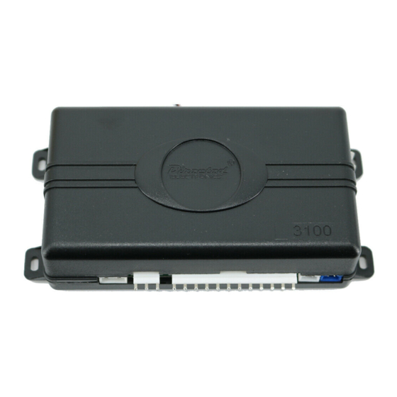
Model 3100
Installation Guide
This product is intended for installation by a professional
installer only! Attempts to install this product by a person other
than a trained professional may result in severe damage to a
vehicle's electrical system and components.
© 2011 Directed Electronics, Vista, CA
N3100 2011 - 12
Advertisement
Table of Contents

Related Manuals for Directed Electronics 3100


Summary of Contents for Directed Electronics 3100
- Page 1 This product is intended for installation by a professional installer only! Attempts to install this product by a person other than a trained professional may result in severe damage to a vehicle’s electrical system and components. © 2011 Directed Electronics, Vista, CA N3100 2011 - 12...
-
Page 2: Table Of Contents
Contents What is Included ....................1 Wiring Connections ..................... 2 Main Harness 12-pin Connector (H1) ............. 2 Door Lock, 3-Pin Connector (H2) ............3 Horn Honk, 3-pin connector ..............3 Starter Interrupt Harness (H3) ............... 4 Plug-in LED and Valet Program switch ............. 4 Internal Programming Jumper ................ -
Page 3: What Is Included
• The plug-in Valet button • An on-board dual zone impact sensor • A high-powered siren • The 12-pin primary harness • The 3-pin door lock harness • The plug-in starter interrupt harness © 2011 Directed Electronics. All rights reserved. -
Page 4: Wiring Connections
(-) Door Trigger Input, Zone 3 H1/6 BLUE (-) Multiplex Trigger Input, Zone 1 H1/7 VIOLET (+) Door Trigger Input, Zone 3 H1/8 BLACK (-) Chassis Ground Input H1/9 YELLOW (+) Ignition Input, Zone 5 © 2011 Directed Electronics. All rights reserved. -
Page 5: Door Lock, 3-Pin Connector (H2)
If the vehicle has a (+) horn circuit, a standard automotive SPDT relay or a relay assembly package (p/n 8617) must be used. © 2011 Directed Electronics. All rights reserved. -
Page 6: Starter Interrupt Harness (H3)
2-pin connector. The status LED and valet switch each fit into a 9/32 inch hole. Valet Program button Blue 2-pin port Control Module White 2-pin port © 2011 Directed Electronics. All rights reserved. -
Page 7: Internal Programming Jumper
For parking light circuits that draw 10 amps or more, the internal P/N 8617 jumper must be switched to a (-) light flash output. or a standard au- tomotive SPDT relay must be used on the H1/2 light flash output harness wire. © 2011 Directed Electronics. All rights reserved. -
Page 8: Onboard Dual Stage Zone 2 Impact Sensor
This is ideal for add-on remote starters and window control modules: ADD-ON REMOTE START UNIT © 2011 Directed Electronics. All rights reserved. -
Page 9: Nuisance Prevention Circuitry (Npc)
(-) multiplex trigger input H1/6 Blue wire Instant trigger: a heavier impact On-board shock sensor. detected by the on-board shock sensor Door switch trigger H1/5 Green and H1/7 Violet Ignition trigger H1/9 Yellow wire © 2011 Directed Electronics. All rights reserved. -
Page 10: Remote Control Programming
The siren emits one quick chirp, and then another lengthier chirp when exiting. Programming is exited if any of the following occurs: • Turn ignition off • Close the doors • Press Valet button too many times • 15 seconds or more lapses between steps © 2011 Directed Electronics. All rights reserved. -
Page 11: Function Table
Valet button once more and hold it. The LED flashes and the siren sounds to confirm the selection. While still holding the Valet button press the button on the © 2011 Directed Electronics. All rights reserved. -
Page 12: Feature Table
3.5 Second Door Lock Pulse Double Pulse Unlock OFF Double Pulse Unlock ON Code Hopping ON Code Hopping OFF Door Trigger Error Chirp ON Door Trigger Error Chirp OFF Double Pulse Lock OFF Double Pulse Lock ON © 2011 Directed Electronics. All rights reserved. -
Page 13: Feature Descriptions
Passive Locking: The doors automatically lock when the system pas- sively arms. Door Lock Pulse • 0.8 seconds: the door lock output pulses are 800mS in duration. • 3.5 seconds: the door lock pulses are 3.5 seconds in duration. Double Pulse Unlock © 2011 Directed Electronics. All rights reserved. - Page 14 The alarm system does not monitor zone inputs for bypass notification, Warn Away, or full trigger inputs - until the 20 second timer is completed. This avoids any false system triggering while the windows are in motion. © 2011 Directed Electronics. All rights reserved.
-
Page 15: Troubleshooting
Is the Yellow H1/9 ignition wire connected to true ignition? Wire must be powered in the run and start positions in order to work properly. © 2011 Directed Electronics. All rights reserved. - Page 16 The company behind this system is Directed Electronics Since its inception, Directed Electronics has had one purpose, to provide consum- ers with the finest vehicle security and car stereo products and accessories available. The recipient of nearly 100 patents and Innovation Awards in the field of advanced electronic technology.
Need help?
Do you have a question about the 3100 and is the answer not in the manual?
Questions and answers
install avital 1300 on dodge Durango 2001 Door lock single wire
To install the Directed Electronics Avital 1300 on a 2001 Dodge Durango using a single wire for door lock:
1. Use the Door Lock 3-Pin Connector (H2).
2. Connect the GREEN wire from H2 pin 1 to the vehicle’s lock/unlock wire. The GREEN wire provides (-) lock and (+) unlock output.
3. Confirm if the vehicle's lock system matches the system’s output type. If not, a 451M Door Lock Relay Satellite or two relays may be needed.
4. Ensure all other wiring (power, ignition, ground, siren output) is connected properly according to the main harness (H1) pinout.
Important: Professional installation is recommended.
This answer is automatically generated