Table of Contents
Advertisement
www.proform.com
Model No. PFTL39508.0
USER'S MANUAL
Serial No.
Write the serial number in the space
above for future reference.
Serial
Number
Decal
QUESTIONS?
As a manufacturer, we are com-
mitted to providing complete cus-
tomer satisfaction. If you have
questions, or if parts are missing,
PLEASE DO NOT CONTACT
THE STORE; please contact
Customer Care.
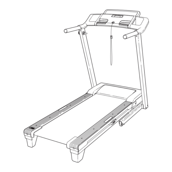
IMPORTANT: You must note the
product model number and
serial number (see the drawing
above) before contacting us:
1-888-533-1333
CALL TOLL-FREE:
Mon.–Fri. 6 a.m.–6 p.m. MST
Sat. 8 a.m.–4 p.m. MST
ON THE WEB:
www.proformservice.com
CAUTION
Read all precautions and instruc-
tions in this manual before using
this equipment. Save this manual
for future reference.
Advertisement
Table of Contents

Subscribe to Our Youtube Channel
Related Manuals for ProForm 380 E


Summary of Contents for ProForm 380 E
- Page 1 www.proform.com Model No. PFTL39508.0 USER'S MANUAL Serial No. Write the serial number in the space above for future reference. Serial Number Decal QUESTIONS? As a manufacturer, we are com- mitted to providing complete cus- tomer satisfaction. If you have questions, or if parts are missing, PLEASE DO NOT CONTACT THE STORE;...
-
Page 2: Table Of Contents
TABLE OF CONTENTS WARNING DECAL PLACEMENT ............. .2 IMPORTANT PRECAUTIONS . -
Page 3: Important Precautions
IMPORTANT PRECAUTIONS WARNING: To reduce the risk of serious injury, read all important precautions and in- structions in this manual and all warnings on your treadmill before using your treadmill. ICON as- sumes no responsibility for personal injury or property damage sustained by or through the use of this product. - Page 4 19. Never leave the treadmill unattended while it 23. Inspect and properly tighten all parts of the is running. Always remove the key, unplug treadmill regularly. DANGER: the power cord, and switch the reset/off cir- cuit breaker to the off position when the Always unplug the power treadmill is not in use.
-
Page 5: Before You Begin
380 E model number and serial number before contacting us. ® treadmill. The 380 E treadmill offers a selection of fea- The model number and the location of the serial num- tures designed to make your workouts at home more ber decal are shown on the front cover of this manual. -
Page 6: Assembly
ASSEMBLY To hire an authorized service technician to assemble the treadmill, call 1-800-445-2480. Assembly requires two persons. Set the treadmill in a cleared area and remove all packing materials. Do not dispose of the packing materials until assembly is completed. Note: The underside of the treadmill walking belt is coated with high-performance lubricant. - Page 7 1. Make sure that the power cord is unplugged. Hole With the help of a second person, carefully tip the treadmill onto its left side. Partially fold the Frame (48) so that the treadmill is more stable; do not fully fold the Frame yet. Cut the tie securing the Wire Harness (77) to the Base (85).
- Page 8 3. Attach a Wheel (86) to the Base (85) with an M10 x 50mm Bolt (27) and an M10 Nut (33). Do not overtighten the Nut; the Wheel must turn freely. 4. Identify the Right Upright (78) and the Right Upright Spacer (80), which are marked with Wire stickers.
- Page 9 6. Press a Base Cap (82) into the Base (85). 7. With the help of a second person, carefully tip the treadmill onto its right side. Partially fold the Frame (48) so that the treadmill is more stable; do not fully fold the Frame yet. Attach a Wheel (86) to the Base (85) with an M10 x 50mm Bolt (27) and an M10 Nut (33).
- Page 10 8. With the help of a second person, hold a Bolt Spacer (79) inside the lower end of the Left Upright (73). Insert an M10 x 96mm Bolt (5) with an M10 Star Washer (8) into the Left Upright and the Bolt Spacer.
- Page 11 11. Attach the Left Handrail (89) to the console as- sembly with three M4.2 X 19mm Screws (1). Start all three Screws before tightening any Console of them; do not overtighten the Screws. Assembly 12. Have a second person hold the console assem- bly near the Right Upright (78).
- Page 12 13. Partially tighten four M8 x 25mm Bolts (6) with four M8 Star Washers (10) into the Uprights (73, 78) and the Handrails (89, 90). Then, tighten all four Handrail Bolts. See steps 5 and 8. Tighten the four M10 x 96mm Bolts (5).
-
Page 13: Operation And Adjustment
OPERATION AND ADJUSTMENT THE PRE-LUBRICATED WALKING BELT tric shock. This product is equipped with a cord having an equipment-grounding conductor and a grounding plug. Plug the power cord into a surge suppressor, Your treadmill features a walking belt coated with high- performance lubricant. - Page 14 CONSOLE DIAGRAM Clip FEATURES OF THE CONSOLE see page 17. To use the information mode, see page 18. The treadmill console offers an impressive array of IMPORTANT: If there is a sheet of clear plastic on features designed to make your workouts more effec- the console, remove the plastic.
-
Page 15: Turn On Power
HOW TO TURN ON THE POWER HOW TO USE THE MANUAL MODE IMPORTANT: If the treadmill has been exposed to 1. Insert the key into the console. cold temperatures, allow it to warm to room tem- perature before turning on the power. If you do not See HOW TO TURN ON THE POWER at the left. - Page 16 5. Follow your progress with the displays. 6. Measure your heart rate if desired. The lower left display— Before using the As you exercise, the handgrip pulse lower left display can sensor, remove show the elapsed time the sheets of and the distance that you clear plastic from have walked or run.
- Page 17 HOW TO USE A PRESET WORKOUT ment. Note: The same speed setting and/or incline setting may be programmed for consecutive seg- 1. Insert the key into the console. ments. See HOW TO TURN ON THE POWER on page 15. Tones will sound at the end of each segment. Three seconds before the speed and/or incline of 2.
- Page 18 THE INFORMATION MODE The upper display will show the total number of hours the The console features an information mode that keeps treadmill has been used. track of the total distance that the walking belt has moved and the total number of hours that the treadmill has been used.
-
Page 19: How To Fold And Move The Treadmill
HOW TO FOLD AND MOVE THE TREADMILL HOW TO FOLD THE TREADMILL FOR STORAGE Before folding the treadmill, adjust the incline to the lowest position. If you do not do this, you may damage the treadmill when you fold it. Remove the key and unplug the power cord. - Page 20 HOW TO LOWER THE TREADMILL FOR USE 1. Hold the upper end of the treadmill with your right hand. Pull the latch knob to the left and hold it. Pivot the frame down until it is past the latch pin. Then, release the latch knob.
-
Page 21: Troubleshooting
TROUBLESHOOTING Most treadmill problems can be solved by following the steps below. Find the symptom that applies, and follow the steps listed. If further assistance is needed, please see the front cover of this manual. PROBLEM: The power does not turn on SOLUTION: a. - Page 22 Remove the three M4.2 x 19mm Hood Screws (13) and carefully pivot the Motor Hood (53) off. Locate the Reed Switch (54) and the Magnet (42) on the left side of the Pulley (44). Turn the Pulley until the Magnet is aligned with the Reed Switch. 1/8 in.
- Page 23 PROBLEM: The walking belt is off-center or slips when walked on SOLUTION: a. If the walking belt is off-center, first remove the key and UNPLUG THE POWER CORD. If the walking belt has shifted to the left, use the hex key to turn the left idler roller bolt clockwise 1/2 of a turn;...
-
Page 24: Exercise Guidelines
EXERCISE GUIDELINES WARNING: Burning Fat—To burn fat effectively, you must exer- cise at a low intensity level for a sustained period of Before beginning this time. During the first few minutes of exercise, your or any exercise program, consult your physi- body uses carbohydrate calories for energy. - Page 25 SUGGESTED STRETCHES The correct form for several basic stretches is shown at the right. Move slowly as you stretch—never bounce. 1. Toe Touch Stretch Stand with your knees bent slightly and slowly bend forward from your hips. Allow your back and shoulders to relax as you reach down toward your toes as far as possible.
-
Page 26: Part List
PART LIST—Model No. PFTL39508.0 R0908A To locate the parts listed below, see the EXPLODED DRAWING near the end of this manual. Key No. Qty. Description Key No. Qty. Description M4.2 x 19mm Screw Left Foot M4.2 x 25mm Tek Screw Right Foot Idler Roller Motor Hood... - Page 27 Key No. Qty. Description Key No. Qty. Description – 8" Blue Wire, 2F – 6" Red Wire, M/F – 6" Blue Wire, M/F – 6" Black Wire, M/F – 6" Blue Wire, 2F – Userʼs Manual Note: Specifications are subject to change without notice. See the back cover of this manual for information about ordering replacement parts.
-
Page 28: Exploded Drawing
EXPLODED DRAWING A—Model No. PFTL39508.0 R0908A... - Page 29 EXPLODED DRAWING B—Model No. PFTL39508.0 R0908A...
- Page 30 EXPLODED DRAWING C—Model No. PFTL39508.0 R0908A...
- Page 31 EXPLODED DRAWING D—Model No. PFTL39508.0 R0908A...
-
Page 32: Ordering Replacement Parts
ORDERING REPLACEMENT PARTS To order replacement parts, please see the front cover of this manual. To help us assist you, be prepared to pro- vide the following information when contacting us: • the model number and serial number of the product (see the front cover of this manual) •...
Need help?
Do you have a question about the 380 E and is the answer not in the manual?
Questions and answers