Table of Contents
Advertisement
Quick Links
®
Owners Manual
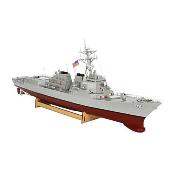
Specifications
Length ........................................................................................ 43 in (1090mm)
Beam .............................................................................................. 6 in (156mm)
Motor ...............................................................................................390-size (x2)
Weight ...............................................................................................5 lb(2.3 kg)
Speed Control ........................................................ 50-amp waterproof with reverse
Hull Material .......................................................................... Fiberglass composite
Battery ............................................ 7.2V sub-C w/ Tamiya connector (not included)
Radio ............................................................................... 2-channel (not included)
Servo ................................................................. Standard steering servo (installed)
www.ProBoatModels.com
Advertisement
Table of Contents

Related Manuals for ProBoat Arleigh Burke Class Destroyer


Summary of Contents for ProBoat Arleigh Burke Class Destroyer
-
Page 1: Specifications
® Owners Manual Specifications Length ..................43 in (1090mm) Beam ....................6 in (156mm) Motor ....................390-size (x2) Weight ....................5 lb(2.3 kg) Speed Control ............50-amp waterproof with reverse Hull Material ................Fiberglass composite Battery ..........7.2V sub-C w/ Tamiya connector (not included) Radio ................ -
Page 2: Table Of Contents
Table of Contents Table of Contents ....................2 Using the Manual ....................2 Recommended Tools and Adhesives ................ 2 Recommended Radio Equipment and Batteries ............3 General Guidelines and Safety Precautions .............. 3 Unpacking Your Model ................... 4 Basic Assembly ....................7 Accessory Installation .................. -
Page 3: Recommended Radio Equipment And Batteries
Recommended Radio Equipment and Batteries Pro Boat 27MHz radios You will need a 2-channel transmitter and receiver. We recommend one of the crystal- • Pro Boat AM 2-Stick Radio (PRB8021) ® free, interference-free Spektrum , Pro Boat ™ • Pro Boat AM Pistol-Grip (PRB8040) ®... -
Page 4: Unpacking Your Model
Unpacking Your Model Your model must be removed carefully from the packaging to avoid damage. Follow the steps shown to remove your model. Required Tools Hobby knife or similar Side cutter 1. Use a knife to cut the tape that ... - Page 5 4. Carefully lift the rear foam support. Lift the support straight up and out of the box. 7. Carefully lift the main tower and its packaging from the box. 5. Use side cutters to trim the wire ties at ...
- Page 6 9. Remove the ties from the main tower. 12. Use side cutters to cut the ties that secure the secondary tower and accessories to the packaging. Make sure to support the tower so it doesn't drop and become damaged once the ties have been cut.
-
Page 7: Basic Assembly
Basic Assembly The following steps will prepare your model 2. Plug the lead from the speed control for operation. Although there are a lot of into the throttle port of the receiver. details that can be installed, they are not The lead from the rudder servo will plug necessary to operate you model. - Page 8 5. Place the motor battery in the hull. 7. Check the operation of the rudders in The supports are cut to fit a 6-cell battery relationship to the steering wheel. When snug in the hull. the wheel is rotated clockwise, the rudders must move right as shown.
- Page 9 7. Check the operation of the propellers 8. Once the radio is installed and in relationship to the throttle trigger. operating properly, the main tower, When the trigger is pulled in, the right secondary tower and helicopter covers propeller must rotate clockwise and the can be placed in their respective positions left propeller will rotate counterclockwise...
-
Page 10: Accessory Installation
Accessory Installation The installation of the accessories is not 2. Accessory item B and location. mandatory, but will add some incredibly scale appeal to your model. There are a lot of items to install, so take your time and take frequent breaks to avoid frustration when working with all the small parts. - Page 11 4. Accessory item D and location. 6. Accessory item F and location. 5. Accessory item E and location. Use a pin vise and 5/64-inch (2mm) drill bit to enlarge the hole in the hull for the accessory as shown before installation.
- Page 12 7. Accessory item G and location. 8. Accessory item H and location. ...
- Page 13 9. Accessory item I and location. 10. Accessory item J and location. ...
- Page 14 11. Accessory item K and location. 13. Accessory item M and location. 12. Accessory item L and location. ...
- Page 15 14. Accessory item N and location. 15. Two of the N items will be placed on accessory R as shown.
- Page 16 16. Accessory item O and location. 17. Accessory item P, Q and R and locations.
- Page 17 18. Accessory item S and location. 20. The following accessories do not have designation letters associated with them. Use the following images to install these items. 19. Accessory items T and Y and location. 1. Step text and photo. ...
-
Page 18: Warranty And Repair Policy
Warranty and Repair Policy Age Recommendation (c) Purchaser Remedy- Horizon's sole obligation hereunder shall be that Horizon 14 years or over. This is not a toy. This will, at its option, (i) repair or (ii) replace, product is not intended for use by children any Product determined by Horizon to be without direct adult supervision. -
Page 19: Warranty Services
Warranty Services Questions, Assistance, and Repairs Warranty Inspection and Repairs Your local hobby store and/or place of To receive warranty service, you must include purchase cannot provide warranty support your original sales receipt verifying the or repair. Once assembly, setup or use of proof-of-purchase date. -
Page 20: Warranty Services
Warranty Services United States Germany Electronics and engines requiring inspection Electronics and engines requiring inspection or repair should be shipped to the following or repair should be shipped to the following address: address: Horizon Service Center Horizon Technischer Service 4105 Fieldstone Road Hamburger Strasse 10 Champaign, Illinois 61822 25335 Elmshorn... -
Page 21: Compliance Information For The European Union
Compliance Information for the European Union Declaration of Conformity Instructions for Disposal of WEEE by Users in the (in accordance with European Union ISO/IEC 17050-1) This product must not be disposed No. HH20100304 of with other waste. Instead, it is the user’s responsibility to dispose of their waste equipment by handing it over to Product(s):... -
Page 22: Replacement Parts
® Replacement Parts Go to ProBoatModels.com to see photos of the replacement parts listed under Arleigh Burke- Class Destroyer. If you have any questions concerning the setup or running of your model, please see page 20 to contact the appropriate Horizon service center. PRB3351 Hull Only PRB3368...
Need help?
Do you have a question about the Arleigh Burke Class Destroyer and is the answer not in the manual?
Questions and answers