
Related Manuals for D-Link DFE-680TX


Summary of Contents for D-Link DFE-680TX
- Page 1 DFE-680TX Fast Ethernet PC card for CardBus User’s Guide Rev. 02 (March, 2001) RECYCLABLE Printed in Taiwan...
-
Page 2: Table Of Contents
Troubleshooting the Hardware Installation ..............34 Verify Each Computers Identification................34 Verify Network Adapter Installation................34 Verify Cable Connections ..................... 35 Understanding Indicators ....................36 Diagnostics and Checking Communicati o ns ..............36 Pinging your DFE-680TX Card..................37 Specifications ........................38... -
Page 3: Introduction
Thank you for choosing D-Link DFE-680TX, the value leader among Ethernet / Fast Ethernet adapters for CardBus notebook PCs. This chapter provides a general description of DFE-680TX features, with a summary of features at the end of the chapter. Installation instructions are given in Chapters 2 and 3. -
Page 4: About Fast Ethernet
• 100Base-T4 (using four twisted pairs in a Category 3, Category 4, or Category 5 UTP cable) 100Base-FX (using two fiber-optic strands). The DFE-680TX provides half-duplex 100Base-TX operation (in Category 5 twisted-pair cable environments). It does not provide 100Base-T4 or 100Base-FX operation. To... - Page 5 If the supporting device does not have autonegotiation functionality, then its monotone (single capability) message will be recognized by the DFE-680TX’s autonegotiation facility, and the DFE-680TX will simply switch to the one of its own capabilities which matches that of the supporting device.
-
Page 6: Led Indicators
• Ln/Act Indicator: Steady green indicates that there is good linkage to the network ("Linkage" state, quiescent). Flashing green indicates that the DFE-680TX is transmitting or receiving ("Activity" state). In 10Mbps mode, flashing will be regular and periodic. In 100 Mbps mode, flashing may be irregular, with longer dark periods during heavy traffic activity. - Page 7 • Laser-welded stainless steel case • RJ-45 connector with auto-detection of network speed • Software support: Diagnostic Program NetWare DOS ODI NetWare Lite Personal NetWare Windows 95 OSR2 Windows NT 3.51 Windows NT 4.0 Packet Driver for NCSA Packet Driver for FTP PC/TCP Packet Driver for IPX Packet Driver for Winsock Windows 98...
-
Page 8: Hardware Installation
DFE-680TX. Open the shipping carton and carefully remove all items. In addition to this User's Guide, ascertain that you have: •... -
Page 9: Step 1: Insert The Dfe-680Tx
In the subsequent procedure for DFE-680TX software installation, it might be useful for you to know whether your DFE-680TX is installed in Slot 1 or Slot 2. Under Windows 95, you can check by opening the Control Panel / PC Card display. -
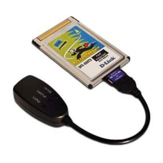
Page 10: Step 2: Attach The Media Coupler
The back-end receptacle of the DFE-680TX remains accessible (approximately flush with the case of the computer) when the DFE-680TX is properly seated in its PC Card slot. Taking care to keep the top side of the media coupler plug up, insert the plug into the DFE-680TX's receptacle until it is firmly seated and latched. -
Page 11: Step 4: Confirm Connection (Ln/Act Indicator)
Step 4: Confirm Connection (Ln/Act Indicator) When the notebook computer's power is ON, the DFE-680TX is firmly seated in the slot connector, the media adapter plug is firmly engaged (and latched) in the back-end receptacle of the DFE-680TX, the media adapter has a good cable connection to the supporting hub, and the supporting hub is power on and functioning properly, then the media coupler’s Ln/Act LED glows steady green ("Linkage"... -
Page 12: Remove The Dfe-680Tx
PC Card slot. The media coupler plug is held in place by small latching hooks at either side of the plug. To remove the media coupler plug from the DFE-680TX, it is necessary to unlatch the hooks by depressing the two small latch wings of the plug. Use thumb and forefinger to squeeze the latch wings into the plug body and gently pull the plug out of its receptacle. -
Page 13: Connect The Network Cable
Category 5 UTP cable is required for Fast Ethernet operation. The maximum length of cable between the DFE-680TX and the supporting hub is 300 ft. The cable must be “ straight” (not a“crossover” cable), with an RJ-45 plug at each end. Make the network connection by plugging one end of the cable into the RJ-45 receptacle of the media coupler, and the other end into a port of the supporting hub. -
Page 14: Connecting For 10Mbps Ethernet
STP cable, all qualify under traditional Ethernet cabling rules. The maximum cable run between the DFE-680TX and the supporting hub is 300 ft. The cable must be “straight” (not a “ crossover” cable) with RJ-45 plug at each end. Make the network connection by plugging one end of the cable into the RJ-45 receptacle of the media coupler, and the other end into a port of the supporting hub. -
Page 15: Software Installation
Software Installation Windows2000 driver install Figure1- Insert DFE-680TX into notebook, new hardware device should prompt. Select Next. - Page 16 Figure2- Select Next to continue installation.
- Page 17 Figure3- Ensure that the Specify location box is checked and click Next...
- Page 18 Figure4- Click Next to continue...
- Page 19 Figure5- The Digital Signature Not Found window appears. Click Yes to continue.
- Page 20 Figure6- Click Finish to complete the DFE-680TX Ethernet Card installation.
-
Page 21: Check In Device Manager For Proper Installation For Win2000
Device Manager for proper installation for Win2000 Figure7- Click the Start button > Settings > Control Panel >Then Double Click the System icon and the Systems Properties should appear. - Page 22 Figure8- Select Hardware and then click the Device Manager button...
- Page 23 Figure9- The Device Manager menu. Double click on the Network Adapters and the D-Link DFE-680 CardBus should appear showing proper installation.
-
Page 24: Windows Me Driver Installation
Windows ME driver installation Figure1- Insert the DFE-680TX into available PCMCIA slot. Windows should detect Card. The Add New Hardware windows appears, select Next... - Page 25 Figure2- Enter CD-ROM drive letter or click on the Browse button and highlight the CD-ROM drive under Drivers. Then Click Next to continue the installation.
- Page 26 Figure3- A screen appears telling you that is has located the DFE-680TX driver in the CD-ROM drive. Then click Next, Windows will copy files to the hard drive.
- Page 27 Figure4- Click Finish to complete driver installation.
- Page 28 Figure5- Click the start button > Settings > Control Panel > Click the System button > Device Manager > Network Adapters. And D-Link DFE-680TX CardBus should appear showing proper installation.
-
Page 29: Windows 98 Driver Install
Windows 98 Driver install Figure1- Select Next. - Page 30 Figure2- Select Next...
- Page 31 Figure3- Enter CD-ROM drive, or click on the Browse button and select CD-ROM drive.
- Page 32 Figure4- Driver file name, select Next. Figure5- Insert 98 CD-ROM then click on OK button.
- Page 33 Figure6- Enter CD-ROM drive, then type D:\ Win98 in the box. (Some computers will have the Windows 98 files available in the C: \ Windows\ options\ cabs directory. )After typing in the location. Click OK.
- Page 34 Figure7- Finish...
- Page 35 Figure8- Click the Start button > Setting > Control Panel > Click the System button > Device Manager > Network Adapters. Device Manager will display of proper installation of adapter.
-
Page 36: Troubleshooting
If you see symbols such as yellow exclamation point or red “X” over the icon adjacent to “D-Link DFE-680TX/TXD CardBus PC Card,” your card is not installed properly or may have a problem. Double-click the “ D-Link DFE-680TX/TXD CardBus PC Card... -
Page 37: Verify Cable Connections
Check to see that the computer(s) you are troubleshooting are properly connected. Each computer must be connected from its DFE-680TX with a Category 5 cables. Examine the network cables and ensure that they have not been damaged by walking-on, rolling over chairs, or closed in doors. -
Page 38: Understanding Indicators
Your DFE-680TX has indicators or lights that can give you information about your network traffic and help you determine problems when troubleshooting. Your DFE-680TX has two indicators label “ACT” and “LINK” on their back panels. A steady green “LINK” light indicates a good connection with the hub. A flashing green “ACT”... -
Page 39: Pinging Your Dfe-680Tx Card
Pinging your DFE-680TX Card Follow these steps to Ping a device: Ping is the acronym for Packet Internet Groper (PING), a utility to determine if a specific IP address is accessible. It works by sending a packet to the specified address and waiting for a reply. -
Page 40: Specifications
Specifications Network Type: Ethernet 100Base-TX Ethernet IEEE 802.3u standard for 100Mbps baseband CSMA/CD local area network Ethernet 10BASE-T Ethernet IEEE 802.3 standard for 10Mbps baseband CSMA/CD local area network Jumperless Hardware Autonegotiation functionality Media interface: RJ-45 LAN Chip Set: ADMTEK AN985L EMI Certifications: FCC Class B VCCI Class B... - Page 41 *Check http://www.dlink.com for newest releases of drivers. D-Link provides free technical support. North American customers can contact D -Link technical support through our web site, e-mail, or by phone. North American technical support is available Monday through Friday from 6:00 a.m. to 6:00 p.m. (PST).
- Page 42 FCC Certifications This equipment has been tested and found to comply with the limits for a Class B digital device, pursuant to Part 15 of the FCC Rules. These limits are designed to provide reasonable protection against harmful interference in a residential installation. This equipment generates, uses and can radiate radio frequency energy and, if not installed and used in accordance with the instructions, may cause harmful interference to radio communications.
- Page 43 VCCI Warning...
-
Page 44: Limited Warranty
Such repair or replacement will be rendered by D-Link at an Authorized D-Link Service Office. The replacement Hardware need not be new or of an identical make, model or part; D-Link may in its discretion may replace the defective Hardware (or any part thereof) with any reconditioned product that D -Link reasonably determines is substantially equivalent (or supe rior) in all material respects to the defective Hardware. - Page 45 RMA number is not visible from the outside of the package. The product owner agrees to pay D-Link’s reasonable handling and return shipping charges for any product that is no t packaged and shipped in accordance with the foregoing requirements, or that is determined by D-Link not to be defective or...
- Page 46 WARRANTY SERVICE) RESULTING FROM THE USE OF THE PRODUCT, RELATING TO WARRANTY SERVICE, OR ARISING OUT OF ANY BREACH OF THIS LIMITED WARRANTY, EVEN IF D-LINK HAS BEEN ADVISED OF THE POSSIBILITY OF SUCH DAMAGES. THE SOLE REMEDY FOR A BREACH OF THE FOREGOING LIMITED WARRANTY IS REPAIR, REPLACEMENT OR REFUND OF THE DEFECTIVE OR NON- CONFORMING PRODUCT.
- Page 47 Some states do not allow exclusion or limitation of incidental or consequential damages, or limitations on how long an implied warranty lasts, so the foregoing limitations and exclusions may not apply. This limited warranty provides specific legal rights and the product owner may also have other rights which vary from state to state.
- Page 48 TEL: 39-02-2900-0676 FAX: 39-02-2900-1723 URL: www.dlink.it E-MAIL: info@dlink.it JAPAN D-LINK JAPAN 10F, 8-8-15 Nishi-Gotanda, Shinagawa-ku, Tokyo 141 Japan TEL: 81-3-5434-9678 FAX: 81-3-5434 -9868 URL: www.d-link.co.jp RUSSIA D-LINK RUSSIA Michurinski Prospekt 49, 117607 Moscow, Russia TEL: 7-095-737-3389, 7-095-737-3492 FAX: 7-095-737-3390 SINGAPORE D-LINK INTERNATIONAL...
Need help?
Do you have a question about the DFE-680TX and is the answer not in the manual?
Questions and answers