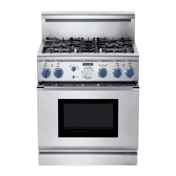
Thermador PD304 Installation Instructions Manual
Professional dual fuel ranges
Hide thumbs
Also See for PD304:
- Care and use manual (144 pages) ,
- Installation instructions manual (72 pages) ,
- Care and use manual (48 pages)

Subscribe to Our Youtube Channel
Related Manuals for Thermador PD304


Summary of Contents for Thermador PD304
- Page 1 F o r T h e r m a d o r ® P r o f e s s i o n a l D u a l F u e l R a n g e s PD304 PD36 PD48...
- Page 2 PLEASE READ ENTIRE INSTRUCTIONS BEFORE PROCEEDING IMPORTANT: Save these instructions for the Local Gas Inspector’s use. INSTALLER: Please leave these Installation Instructions with this unit for the owner. OWNER: Please retain these instructions for future reference. WARNING For Massachusetts Installations: Disconnect power before installing.
-
Page 3: Table Of Contents
Model PD304 Model PD364GL Model PD484GG Low Back Model LB36R Low Back Model LB48R Contents Introduction ................2 Important Installation Information ..........3 Step 1: Ventilation Requirements ..........4 Step 2: Cabinet Preparation ..........5 – 9 Step 3: Unpacking, Moving and Placing the Range ........ -
Page 4: Introduction
Ranges are free stand- ing units available in a number of configurations. CAUTION Model PD304 is equipped with four sealed gas When connecting the unit to propane gas, surface burners and a 30-inch electric convection make certain the propane gas tank is equipped self-cleaning oven with broil capability. -
Page 5: Important Installation Information
Important Installation Information This appliance has been tested in accordance with CAUTION: ANSI Z21.1 Current Issue Standard for Household Cooking Appliances (USA). (1) When connecting the unit to propane gas, It is strongly recommended that this appliance be make certain the propane gas tank is installed in conjunction with a suitable overhead equipped with its own high pressure regu- vent hood. -
Page 6: Step 1: Ventilation Requirements
** Thermador offers a choice of remote (VTR1000Q or VTR1400Q) or in-hood (VTN1000Q) blowers for use in wall installations. -
Page 7: Step 2: Cabinet Preparation
2. The 36" ranges may be recessed into the cabi- clearance to combustible material ∆ is over 12", nets beyond the edge of the front face of the a Thermador Island Trim may be used. (See Fig. oven (See Figures 2A and 2B). 2B). Figures 2A and 2B indicate the space required for each type of backguard. - Page 8 Step 2: Cabinet Preparation CAUTION: Do not install the Models PD30 and PD48 ranges such that the oven door is flush with the cabinet face. A flush installation could result in damage to the cabinets due to exposure to high heat. ∆...
- Page 9 Step 2: Cabinet Preparation FIG. 2A - Side View 3/8" space FIG. 2B - Side View NOTE: For Island trim installations, counter surface should have a cantilever edge meeting the back section of the island trim accessory. 4" Cantilever Countertop NOTE: If an inner wall is used under the cantilever counter top, there...
- Page 10 Step 2: Cabinet Preparation GAS AND ELECTRIC SUPPLY ZONES: FIG. 3A Gas & Electrical Supply Zone for Dual-Fuel Ranges The Dual-Fuel ranges may be con- Typical placement nected to the power supply with a shown. range supply cord kit or by hard- Other placement of Gas wiring to the power supply.
-
Page 11: Step 2: Cabinet Preparation
Step 2: Cabinet Preparation ELECTRICAL SUPPLY, DUAL FUEL RANGES Installation of Dual Fuel ranges must cover, the combined plug/receptacle unit is installed. Refer to Figure 9 on be planned so that the rough-in of the or junction box cover/conduit con- Page 16 for location of junction box junction box for the receptacle or con- nector should protrude no more than... -
Page 12: Step 3: Unpacking, Moving And Placing The Range
Step 3: Unpacking, Moving and Placing the Range CAUTION Chart A 30" Range 36" Range 48" Range Proper equipment and ad- Shipping Weight 335 lbs. 444 lbs. 584 lbs. equate manpower must be used in moving the range to Weight without 285 lbs. -
Page 13: And Placing The Range
Step 3: Unpacking, Moving and Placing the Range • Due to the weight, a dolly with soft wheels Fig. 6- Dolly Positioning should be used to move this unit. The weight must be supported uniformly across the bottom (See Fig. 6). •... -
Page 14: Step 4: Installing Anti-Tip Device
Step 4: Installing Anti-Tip Device For all 30" and 36" ranges, an anti-tip device must be installed as per these instructions. WARNING WARNING RANGE TIPPING HAZARD • All ranges can tip and injury could result. • ALL RANGES CAN To prevent accidental tipping of the range, attach it to the floor, wall or cabinet by installing the Anti-Tip Device supplied. -
Page 15: Step 4: Installing Anti-Tip Device
Step 4: Installing Anti-Tip Device PD30 and PD36 Dual Fuel Ranges (Figures 8A and 8B) Thermador Service Part No. Description 415078 Screw, Phillips, #10 x 1-1/2" 487310 Anti-Tip Bracket, Floor-Mounted IMPORTANT INSTALLATION For walls or floors composed of drywall, sheet- INFORMATION: rock or other soft materials, drill 3/16"... -
Page 16: Step 5: Gas Requirements And Hookup
Contact the dealer where the unit was the back of the unit. Make sure the gas supply is purchased or Thermador (800/735-4328). The field turned off at the manual shut-off valve before conversion kit for all Professional Dual Fuel (PD connecting the appliance. -
Page 17: Step 6: Electrical Requirements
Chart C: Electrical Supply Circuit Requirements MODEL NUMBER VOLTAGE CIRCUIT RATING FREQUENCY PHASE PD304 120/240 VAC 35 Amps 60 Hz. Single PD36 120/240 VAC 40 Amps 60 Hz. - Page 18 Step 6: Electrical Requirements, Connection & Grounding Dual Fuel models must be connected to the power supply utilizing one of the following methods. For all methods of connection, the length of the cord or conduit/wiring must allow the unit to be slid completely out of the cabinet without having to unplug or disconnect the unit from the power supply.
-
Page 19: Connection And Grounding
Step 6: Electrical Requirements, Connection & Grounding A 3- or 4-conductor supply may be connected to the terminal block. Conductor Securement FIG. 10 Upper Nut 3-WIRE LEAD CONNECTION Cupped Washer Supply Wire 1. Remove upper nuts only from the terminal block Flat Washer studs. -
Page 20: Step 7: Backguard Installation
(4) sheet metal screws pro- vided. Backguard Installed Chart E: BACKGUARD KIT MODEL NUMBERS RANGE MODEL NO. 9" STD. LOW BACK 12" LOW BACK 22" HIGH SHELF ISLAND TRIM " PD304 Included with Range HS30R IT30R PD36 LB36R HS36R IT36R PD48 LB48R HS48R... -
Page 21: Step 8: Door Installation
Step 8: Door Installation CAUTION The door is heavy and requires two people to handle it properly. 1. Insert the door hinge into the hinge pocket in the front frame. When the door is properly installed, the bottom edge will be parallel to the front of the range and the hinge will click into position and support the weight of the door. -
Page 22: Step 9: Test And Adjustment
Step 9: Test and Adjustment Install any loose components, sive noise, or lifting of the flame CAUTION such as burner caps and grates, from the burner. If any of these that may have been removed ear- conditions exist, check that the Burner adjustments must be lier. -
Page 23: To Clean And Protect Exterior Surfaces
To Clean and Protect Exterior Surfaces The stainless steel surfaces may be cleaned by DO NOT allow deposits to remain for long periods of wiping with a damp soapy cloth, rinsing with clear time. water and drying with a soft cloth to avoid water DO NOT use ordinary steel wool or steel brushes. -
Page 24: Installer Checklist
Installer Checklist FINAL CHECK LIST Unit tested and free of gas Grill components properly leaks. seated (not all models). Refer Placement of unit. to Use & Care Manual for Gas supply pressure does not Specified clearances main- Grill details. exceed 14" (37mb) W.C. tained to cabinet surfaces. - Page 25 Notes...
- Page 26 Notes...
- Page 27 Notes...
- Page 28 Thermador indicating model number. We reserve the right to change specifications or design without notice. Note: These models are not currently certified for use in Canada. Thermador is not responsible for products which are transported from the United States for use in Canada.
Need help?
Do you have a question about the PD304 and is the answer not in the manual?
Questions and answers