Table of Contents
Advertisement
Quick Links
Download this manual
See also:
Owner's Manual
Advertisement
Table of Contents

Related Manuals for Audiovox MMD154


Summary of Contents for Audiovox MMD154
-
Page 1: Installation Guide
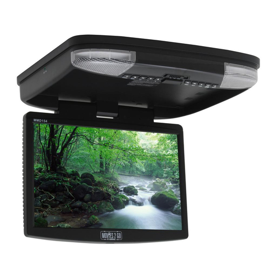
MMD154 15.4" OVERHEAD LCD VIDEO MONITOR WITH DVD PLAYER Installation Guide... -
Page 2: Important Notice
Important Notice An LCD panel and/or video monitor may be installed in a motor vehicle and visible to the driver if the LCD panel or video monitor is used for vehicle information, system control, rear or side observation or navigation. If the LCD panel or video monitor is used for television reception, video or DVD play, the LCD panel or video monitor must be installed so that these features will only function when the vehicle is in “park”... -
Page 3: Materials Included In This Package
MATERIALS INCLUDED IN THIS PACKAGE: 1) MMD154 Video Monitor with DVD player (P/N 136-4447) (1 pc) 2) A/V Adapter Cable (P/N112-3841) (1 pc) 3) Remote Control (P/N 136-4446) (1pc) 4) Hardware Package: • M4.2 x 16mm Phillips Self Tapping ST Pan Head Washer Screws (10 pcs) •... - Page 4 GENERAL INSTALLATION APPROACH: 1) Decide upon system configuration and options that will be installed (i.e.: what components, RF Modu- lator/external amp, remote headphones, DVD, etc.). 2) Review all manuals to become familiar with electrical requirements and hook ups. 3) Decide upon mounting locations of all components and method of mounting. 4) Prep the vehicle by removing any interior trim necessary to gain access to vehicle's wiring as well as all areas where interconnecting wire harnesses will need to be located.
-
Page 5: Vehicle Preparation
VEHICLE PREPARATION: 1) Locate a Battery and accessory power source (+12v when key is in the ACC. and run positions, and 0v when key is off). Also find a location that will provide a good grounding point. Generally, this wire can be found at the ignition switch or fuse-box. -
Page 6: Trim Ring Installation
(or bend) when the mounting screws are tightened. The trim ring MUST be screwed to the unit. (Refer figure 1) Figure 2 Figure 1 2) The MMD154 is now ready to be mounted in the vehicle. (Refer figure 2) Figure 3 Figure 2... - Page 7 Video Unit (5) #8 Flat Washers (5) #8x3/4” Self-Tapping Screws MMD154 PLAYER INSTALLATION 1. Battery + Lead (Yellow)* Connect to the positive terminal of the car battery. 2. ACC Power Lead (Red)* Connect to ACC power, powered when ignition key position is in ACC or run position.
- Page 8 7. AUX A/V, Output An auxiliary A/V output is provided to drive an external monitor. This signal mirrors what's being shown on this player. The volume function does not affect the Auxiliary A/V Output. 8. Polarity Switch Slide to "-" position if your vehicle's door polarity is negative; slide to "+" position if your vehicle's door polarity is positive.
-
Page 9: Troubleshooting
TROUBLESHOOTING SYMPTOM: REMEDY: No power at Video Monitor -Verify +12 VDC on Red wire at Yellow wire Power Harness behind video monitor. Verify ground connection with continuity test from known good ground to black wire at Power Harness Power but no video or sound -Verify that the correct source is selected (DVD, AV 1 or AV 2). - Page 10 © Copyright 2007 AEC 150 Marcus Blvd. Hauppauge, NY 11788 128-7963...
Need help?
Do you have a question about the MMD154 and is the answer not in the manual?
Questions and answers