
Related Manuals for Husqvarna 227R, 227RD, 232R, 232RD, 235R


Summary of Contents for Husqvarna 227R, 227RD, 232R, 232RD, 235R
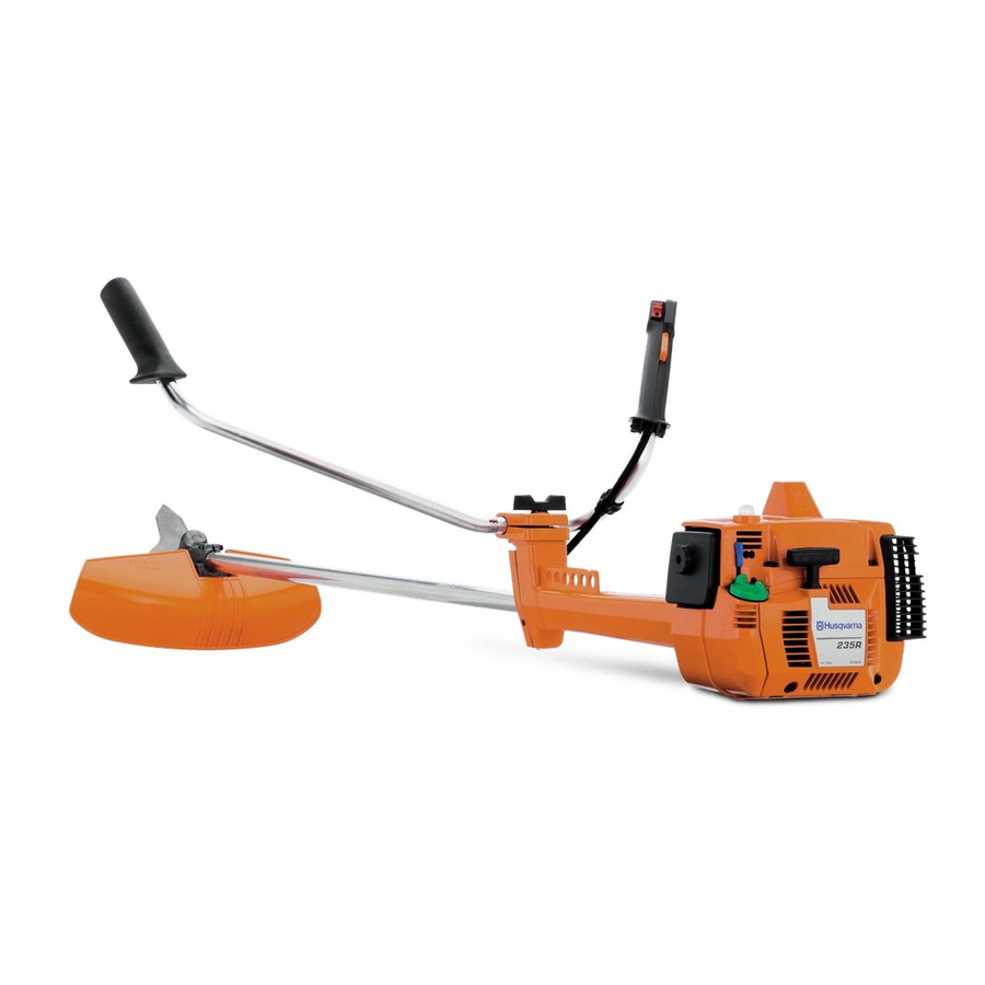
- Page 1 Operator´s manual 227R 227RD 232R 232RD 235R Please read these instructions carefully and make sure English you understand them before using the machine.
-
Page 2: Symbol Explanation
– English Always wear approved protective gloves. Use anti-slip and stable boots. Only use non-metallic, flexible cutting elements, that is trimmer head with trimmer cord. Noise emission to the environment according to the European Community’s Directive. The machine’s emission is specified in chapter Technical data and on label. -
Page 3: Table Of Contents
Husqvarna AB has a policy of continuous product development and therefore reserves the right to modify the design and appearance of products without prior notice. WARNING! Under no circumstances may the design of the machine be modified without the permission of the manufacturer. Always use genuine accessories. -
Page 4: Safety Instructions
IMPORTANT INFORMATION • Incorrect or careless use of a clearing saw, brushcutter or trimmer can turn it into a dangerous tool that can cause serious or even fatal injury to the operator or others. It is extremely important that you read and understand the content of this manual. - Page 5 2. Stop switch The stop switch should be used to stop the engine. 3. Cutting attachment guard This guard is intended to prevent objects from being thrown towards the operator and to protect the operator from unintentionel contact with the cutting attachment. WARNING! Do not attach any blade to the unit without proper installation of all required parts.
-
Page 6: Locking Nut
1) Clearing blades are intended for cutting wood. 2) Grass blades are intended for brush cutting. 3) The trimmer head is intended for trimming grass. 8. Locking nut A locking nut is used to secure some types of cutting equipment on the output shaft. -
Page 7: Control, Maintenance And Service Of The Machine's Safety Equipment
Control, maintenance and service of the machine‘s safety equipment IMPORTANT INFORMATION • All service and repairs to the machine require special training. • This applies especially to the machine‘s safety equipment. If the machine does not meet any of the controls listed below you should contact your service workshop. -
Page 8: Vibration Damping System
3. Cutting attachment guard • Check that the guard is undamaged and not cracked. • Replace the guard if it has been exposed to impact or is cracked. • Always use the prescribed blade an guard combination, see chapter "Technical data". 4. - Page 9 6. Cutting equipment This section describes how through correct maintenance and through using the right type of cutting equipment you can: • Reduce the machine‘s tendency to kickback • Obtain maximum cutting capacity. • Increase the service life of the cutting equipment. Four basic rules: 1)Only use the cutting and guard equipment...
-
Page 10: Trimmer Head
• Make sure the knife positioned on the trimmer guard is intact. This is used to cut the cord to the correct length. • To increase the life of the cord it can be soaked in water for a few days. -
Page 11: Transport And Storage
General safety instructions IMPORTANT INFORMATION • The machine is only designed for trimming grass, brush cutting and/or forestry clearing. • The only accessories to be used with the engine unit as a drive source are the cutting units we recommend in the chapter “Technical data“ . •... -
Page 12: Basic Safety Precautions
General working instructions IMPORTANT INFORMATION • This section takes up the basic safety precautions for working with the clearing saw and trimmer. • If you encounter a situation where you are uncertain how to proceed you should ask an expert. Contact your dealer or your service workshop. -
Page 13: Basic Clearing Techniques
• Grass trimming is a general term for light clearing, e.g. around edges or around trees. A trimmer head or plastic blade is used. WARNING! Sometimes branches, grass or wood can get caught between the guard and cutting equipment. -
Page 14: Forestry Clearing Using A Saw Blade
Clearing‘s ABC Always use the correct equipment. Always have well adjusted equipment. Follow the safety instructions. Organise the work well. Always use full throttle when applying the blade. Always use a sharp blade. Avoid stones. Guide the direction of fall (use the wind). WARNING! Avoid cutting in the cutting region between 12 and 3 o‘clock on the blade. - Page 15 • Large stems must be cut from two sides. Determine in which direction the stem should fall. First apply the saw to the felling side. Then cut from the other side to fell the stem. The feed pressure should be applied with regard to the size of the stem‘s hardness.
- Page 16 – English SAFETY INSTRUCTIONS Trimming • The trimmer is ideal to cut grass that is difficult to reach using a normal lawn mower. Keep the cord parallel to the ground when cutting.
-
Page 17: What Is What
WHAT IS WHAT? 17. Clutch cover 18. Handlebar adjustment 19. Locking nut 20. Support flange 21. Support cup 22. Drive disc 23. Trimmer head 24. Shaft coupling 25. Socket spanner 26. Operator‘s Manual 27. Transport guard 28. Allen key 30. Locking pin 31. -
Page 18: Assembly
Assembling the handlebars (227R/RD, 232R/RD) • Remove the screw at the rear of the throttle handle. • Slide on the throttle handle on the right-hand side of the handlebars, (see the diagram). • Align the hole in the throttle handle for the fixing screw with the hole on the handlebars. -
Page 19: Assembly Of The Blade And Trimmer Head
Assembly of the blade and trimmer head It is extremely important that the disc drive’s/support flange’s guide engages correctly in the cutting equipment’s centre hole when assembling the cutting equipment. Cutting equipment assembled incorrectly can result in serious and/or fatal personal injury. -
Page 20: Assembling The Spray Guard And Trimmer Head
Use the socket spanner in the tool kit. Hold the handle of the spanner as close to the trimmer guard as possible. The nut is tightened when the spanner is turned against the direction of rotation (left-hand thread). • Fit the trimmer head‘s bottom section (K) on the cover (I) by pressing the two sections together with the cut-outs on the bottom section aligned with the catches on the cover. -
Page 21: Assembling And Dismantling The Two-Part Shaft
Assembling and dismantling the two-part shaft (227RD, 232RD) Assembling: • Make sure the handle is loose. • Guide the cut-out on the lower section of the shaft into the coupling‘s locking plate on the upper section of the shaft. The sections are then locked together. -
Page 22: Two-Stroke Oil
Mixing ratio 1:50 (2%). • If HUSQVARNA two-stroke oil is not available you can use a high quality two-stroke oil intended for air cooled engines. Contact your dealer when selecting an oil. Mixing ratio: 1:33 (3%). -
Page 23: Start And Stop
Replace the guard if it is exposed to impact or is cracked. • Check that the trimmer head and spray guard are not damaged or cracked. Replace the trimmer head or spray guard if they are exposed to impact or are cracked. -
Page 24: Maintenance
Carburettor Your Husqvarna product has been designed and manufactured to specifications that reduce harmful emissions. After your unit has been run 8-10 tanks of fuel the engine has broken in. To ensure that your unit is at peak performance and producing the least amount of harmful... -
Page 25: Correctly Adjusted Carburettor
Final setting of the idling speed T Adjust the idling speed with the screw T, If it is necessary to readjust. First turn the idle speed adjusting screw T clockwise until the cutting attachment starts to rotate/ move. Then turn, counter- clockwise until the cutting attachment stops. -
Page 26: Muffler
However, before using the machine you should check that the angle gear is filled to 3/4 with grease. Use HUSQVARNA special grease. Normally, the grease does not need to be changed except when the angle gear... -
Page 27: Air Filter
If the machine is used in dusty conditions the air filter should be soaked in oil, see the section on “Oiling the air filter“. Oiling the air filter Always use HUSQVARNA filter oil, order no. 503 47 73-01. The filter oil contains a solvent to make it spread evenly through the filter. -
Page 28: Sharpening The Clearing Blade
An uncentred blade causes vibrations that can result in damage to the machine. 9. Check that the trimmer head is undamaged and not cracked. Replace the trimmer head if necessary. 10.Check that the locking nut is tight. -
Page 29: Weekly Maintenance
Weekly maintenance 1.Check the starter, the starter cord and the return spring. 2.Make sure that the vibration damping elements are not damaged. 3.Clean the outside of the spark plug. Remove and check the electrode gap. Adjust the gap to 0.5 mm or change the spark plug. -
Page 30: Technical Data
Technical data Engine Cylinder capacity, cm Cylinder bore, mm Stroke length, mm Idling speed, rpm Recommended max. speed, rpm Speed of output axle, rpm Max. engine output, acc. to ISO 8893 Catalytic converter muffler Speed-regulated ignition system Ignition system Manufacturer/type of ignition system Spark plug Electrode gap, mm Fuel lubrication system... - Page 31 Approved accessories 227R/RD Centre hole in blades Ø 20 mm Threaded blade axle M10 Grass blade Saw blade Plastic knifes Trimmer head Edger (RD) Support cup Approved accessories 232R/RD Centre hole in blades Ø 20 mm Threaded blade axle M10...
-
Page 32: Ec Declaration Of Conformity
Husqvarna AB, SE-561 82 Huskvarna, Sweden, tel: +46-36-146500, declare under sole responsibility that the clearing saws Husqvarna 227R/RD, 232R/RD and 235R from 2002's serial numbers and onwards (the year is clearly stated in plain text on the type plate with subsequent serial number), are in conformity with the standards or or other normative documents following the provisions in the COUNCIL'S DIRECTIVES: - of June 22, 1998 ”relating to machinery”... - Page 33 Super Auto II Super Auto II 1 " 4,0 m 15 cm ~2,0 m 6,5 ' 15 cm 6 " 6 " English –...
- Page 34 Tri Cut >20mm >20mm 6 Nm X 10 – English...
- Page 35 Trimmy H II 15 cm 6" 7,5 m ~ 3,7 m 15 cm 6" English –...
- Page 36 Trimmy Hit “Click” ~ 15 cm " – English 15 cm 6 " 7,0 m ~ 3,5 m 12 cm 5" “Click”...
- Page 37 Trimmy Hit Junior 15 cm 6" “Click” 15 cm 6" 5,75 m 15 cm 6" ~ 2,8 m English –...
-
Page 38: Trimmy Hit Pro
Trimmy Hit Pro 15 cm 6" “Click” – English 7,5 m ~ 3,7 m 15 cm 6" 15 cm 6"... - Page 39 Trimmy Hit VI ~ 15 cm " 15 cm " 7,0 m 12 cm 5" ~ 3,5 m “Click” English –...
-
Page 40: Trimmy Sii
Trimmy SII 7,0 m 12 cm 5" ~ 3,5 m ~ 15 cm "Clic" 35-50 NM – English... - Page 41 Trimmy SII ~ 15 cm ~ 15 cm 502 26 04-01 502 25 56-01 502 25 53-01 729 53 27-71 (x3) 738 21 03-04 502 26 24-01 (x2) 740 43 14-00 502 26 03-01 502 25 52-01 502 26 01-01 735 31 19-00 502 27 07-01 502 26 86-01...
- Page 42 ´+H'6¶6*¨...
- Page 43 English –...
- Page 44 114 00 72-26 ´+H'6¶6*¨ 2002W05...
Need help?
Do you have a question about the 227R, 227RD, 232R, 232RD, 235R and is the answer not in the manual?
Questions and answers
Como consertar o fio de corte de corrente e de partida
The provided context does not contain specific instructions for fixing the cutting line. However, for the starting cord:
1. Grip the starter handle and slowly pull out the cord with your right hand until you feel resistance.
2. Quickly and powerfully pull the cord to start the engine.
3. Reset the choke control as soon as the engine fires and repeat if necessary.
4. Once the engine starts, apply full throttle to disengage the start throttle automatically.
5. Do not pull the starter cord out completely or release it from the fully extended position, as this can damage the machine.
This answer is automatically generated