
Subscribe to Our Youtube Channel
Related Manuals for Auto Mate AM6.2


Summary of Contents for Auto Mate AM6.2
- Page 1 Model AM6.2 Installation Guide © 2007 Directed Electronics, Vista, CA N4101A 2007-06...
-
Page 2: Table Of Contents
table of contents what is included ..... . . 3 ors......21 warning! safety first . -
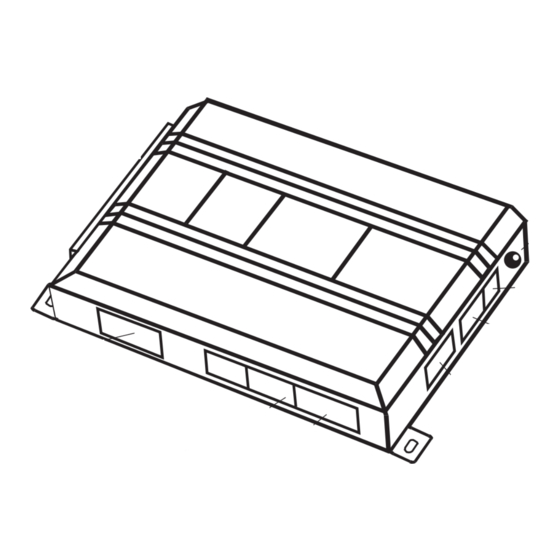
Page 3: What Is Included
what is included ■ The control module (see diagram) ■ Two remote transmitters ■ The plug-in program switch ■ A hood pinswitch ■ A toggle override switch ■ HX antenna receiver 6-pin relay output status LED 2-pin BLUE program plug 3-pin/2-wire door 4-pin satellite/ lock harness... -
Page 4: Warning! Safety First
warning! safety first The following safety warnings must be observed at all times: ■ Due to the complexity of this system, installation of this product must only be performed by an authorized Directed Electronics dealer. ■ When properly installed, this system can start the vehicle via a command signal from the remote control transmitter. -
Page 5: Installation Points To Remember
installation points to remember IMPORTANT! This product is designed for fuel-injected, automatic transmission vehicles only. Installing it in a standard transmission vehicle is dangerous and is contrary to its intended use. Before beginning the installation: ■ Please read this entire installation guide before beginning the installation. The installation of this remote start system requires interfacing with many of the vehicle’s systems. -
Page 6: Finding The Wires You Need
finding the wires you need IMPORTANT! Do not use a 12V test light or logic probe (computer safe test light) to locate these wires! All testing described in this manual assumes the use of a digital multimeter. obtaining constant 12V We recommend two possible sources for 12V constant: The (+) terminal of the battery, or the constant 12V supply to the ignition switch. -
Page 7: Finding The 12V Switched Ignition Wire
5. Cut the wire you suspect of being the starter wire. 6. Attempt to start the car. If the starter engages, reconnect it and go back to Step 3. If the starter does not turn over, you have the right wire. finding the 12V switched ignition wire The ignition wire is powered when the key is in the run or start position. -
Page 8: Finding A (+) Parking Light Wire
finding a (+) parking light wire Most vehicles use a (+) parking light circuit. The (+) parking light wire is often found near the light switch. In many vehicles the light switch is built into the turn signal lever; in these vehicles the parking light wire can be found in the steering column. -
Page 9: Finding The Wait-To-Start Bulb Wire For Diesels
can use a fuel injector control wire for engine speed sensing. Common locations for a tachometer wire are the ignition coil itself, the back of the gauges, engine computers, and automatic transmission computers. IMPORTANT! Do not test tachometer wires using a test light or logic probe. The vehicle will be damaged. -
Page 10: Primary Harness (H1) Wiring Diagram
primary harness (H1) wiring diagram ______ H1/1 LIGHT GREEN/BLACK (-) FACTORY ALARM DISARM ______ H1/2 GREEN/WHITE (-) FACTORY REARM ______ H1/3 YELLOW (+) IGNITION OUT (TO ALARM) ______ H1/4 WHITE/BLUE (-) ACTIVATION INPUT ______ H1/5 GRAY/BLACK (-) WAIT TO START INPUT ______ H1/6 WHITE/RED... -
Page 11: Heavy Gauge Relay Wiring Diagram
heavy gauge relay wiring diagram ______ PINK (+) (30 AMP) OUTPUT TO IGNITION CIRCUIT ______ PURPLE (+) (30 AMP) OUTPUT TO STARTER CIRCUIT ______ ORANGE (+) (30 AMP) OUTPUT TO ACCESSORY CIRCUIT ______ (+) (30A) HIGH CURRENT 12V INPUT ______ PINK/WHITE (+) PROGRAMMABLE OUTPUT FOR ACCESSORY OR IGNITION ______ (+) (30A) HIGH CURRENT 12V INPUT... -
Page 12: Primary Harness (H1), 9-Pin Connector
primary harness (H1), 9-pin connector H1/1 LIGHT GREEN/BLACK (-) factory alarm disarm This wire sends a negative pulse every time the remote start is activated or the doors are unlocked. This can be used to pulse the disarm wire of the vehicle's factory anti-theft device. Use a relay to send a (-) or (+) pulse to the disarm wire as shown in the following diagrams. -
Page 13: H1/5
NOTE: When the activation pulse count can be programmed to 1, 2, or 3 pulses when changed it will affect both activation inputs; the White/Blue, White/Red wire and the remote control activation. H1/5 GRAY/BLACK (-) diesel wait-to-start bulb input Connect this wire to the wire in the vehicle that sends the signal to turn on the WAIT-TO-START bulb in the dash- board. -
Page 14: H1/6
H1/6 WHITE/RED (+) activation input This input comes from the factory set to 1 activation pulse. This means that it is necessary to have one 12V pulse on the white/red wire for the remote start to activate or to deactivate. The same holds true for the remote control activation when set to a one pulse setting it is necessary to press the button once for the remote start to acti- vate or deactivate. -
Page 15: H1/9
H1/9 WHITE (+/-) light flash output IMPORTANT: Do NOT connect this wire to a negative vehicle light flash wire before changing the programming jumper to the negative polarity position or damage to the vehicle light circuit may occur. As factory configured, the H1/9 WHITE wire should be connected to the (+) parking light wire. If the light flash polarity jumper is moved to the (-) position (refer to the Programming Jumper section of this guide), this wire then supplies (-) 200mA output. -
Page 16: 4-Pin Satellite Harness
4-Pin Satellite Harness Blue (-) Status Output When the remote start goes active this wire supplies a (-) 200mA output. It can be used to activate an immo- bilizer bypass or key sense. (-) Accessory Output This output supplies (-) 200mA output to activate additional accessories, you must use a relay inline. (-) 2nd Starter Output This output supplies (-) 200mA output to activate additional starters, you must use a relay inline. -
Page 17: Heavy Gauge Relay Interface
heavy gauge relay interface The heavy gauge wires are used to energize high current circuits in the vehicle. It is crucial that these connec- tions are made correctly so that they are capable of handling the current demands. For this reason, scotch locks, T-taps and other such connectors should not be used. -
Page 18: Remote Start Harness (H2), 5-Pin Connector
remote start harness (H2), 5-pin connector H2/1 BLACK/WHITE neutral safety switch input Connect this wire to the toggle (override) switch as shown in Figure A. Connect the other wire from the toggle switch to the PARK/NEUTRAL switch in the vehicle. This wire will test with ground with the gear selector either in PARK or NEUTRAL. -
Page 19: Neutral Safety Switch Interface
H2/4 GRAY (-) hood pinswitch input This wire MUST be connected to the hood pinswitch. This input will disable or shut down the remote start when the hood is opened. H2/5 BLUE/WHITE (-) status/defogger output This wire supplies a (-) 200mA output as soon as the module begins the remote start process. The H2/5 BLUE/WHITE wire can also be used to activate the defogger trigger (latched/pulsed) 10 seconds after successful remote start. - Page 20 the unit prematurely. You must also connect the H2/4 BROWN (+) shut-down input to the yellow wire on the relay satellite ribbon cable. This prevents the remote start system from activating if the key is left in the “run” position. You must use diodes to isolate the ignition circuit from the brake switch circuit as shown in the diagram below.
-
Page 21: General Motors Trucks, Suvs, And Column Shifting Passenger Cars
general motors trucks, SUVs, and column shifting passenger cars pre-1996 dodge dakota pickups with 2.5 liter motors © 2007 Directed Electronics—all rights reserved... -
Page 22: Bypassing Gm Vehicle Anti-Theft Systems (Vats)
bypassing GM vehicle anti-theft systems (VATS) Vehicles with the GM VATS (Pass Key) systems have a resistor embedded in the ignition key. If the VATS decoder module does not measure the proper resistance when the vehicle is started, the starter and fuel pump may be dis- abled for up to ten minutes. -
Page 23: 1995 And Newer Vehicle Anti-Theft Systems (Immo Bilizers)
1995 and newer vehicle anti-theft systems (immobilizers) 1995 and newer vehicle anti-theft systems (immobilizers) require a bypass module. The bypass module allows for easy interfacing, while still maintaining the OEM system’s integrity. passlock I and passlock II (PL-1 and PL-2) The Passlock I and Passlock II systems can be found in the following General Motors vehicles: ■... -
Page 24: Optional Anti-Grind Relay
will excite the transponder, which is located (but not visible) in the head of the ignition key. The key transpon- der will then send a unique code back to the transceiver for evaluation. If the code matches a valid code of the system, the vehicle will be allowed to start. -
Page 25: Programming Jumpers
programming jumpers light flash (+)/(-) This jumper is used to determine the light flash output polarity. In the (+) position, the on-board relay is enabled and the unit will output (+)12V on the WHITE wire, H1/9. In the (-) position, the on-board relay is disabled. The WHITE wire, H1/9, will supply a 200mA (-) output suitable for driving factory parking light relays. -
Page 26: Plug-In Program Switch
plug-in program switch The Program switch plugs into the blue two-pin connector. transmitter/receiver learn routine The system comes with two transmitters that has been taught to the receiver. The receiver can store up to 4 dif- ferent transmitter codes in memory. Use the following learn routine to add transmitters to the system. The Program switch, plugged into the blue port, is used for programming. - Page 27 auto learn transmitter configuration button one Car Locator RemoteStart/Unlock during start Remote Start CHANNEL NUMBER FUNCTION Auto Learn Delete all transmitters Transmit. While HOLDING the , press the button on the transmitter. Program switch Release. Once the code is learned, the Program switch can be released. You can advance from programming one channel to another by releasing the Program switch and tapping it to advance steps and then holding it.
-
Page 28: Tach Learning
tach learning to learn the tach signal Start the vehicle with the key. DRW-96 Within 5 seconds, press and HOLD the Program switch. The LED will light constant when the tach signal is learned. Release the Program switch. operating settings learn routine The System Features Learn Routine dictates how the unit operates. - Page 29 Transmit. The transmitter is used to select the desired setting. As shipped,the default fea- tures will be in bold in the feature menu. If the feature menu has only two options to choose from, the LED will either turn on or off. On features with multiple choices you will get light flashes indicating which option has been chosen.
-
Page 30: Features Menu
features menu The factory default settings are indicated in bold text in the table below. FEATURE LED ON SETTING LED OFF SETTING NUMBER Engine checking on Engine checking off Tachometer checking type Voltage checking type 12 minutes run time (1)* 24 minutes (2)*, 60 minutes (3) run time Flashing parking light output Constant parking light output... -
Page 31: Feature Descriptions
feature descriptions The features of the system are described below. 1 ENGINE CHECK—ON/OFF: In the default setting the remote start will monitor either the vehicle's tach wire or voltage depending on the programming of Feature 2. If programmed off, the vehicle will crank for the programmed crank time (Feature 5) and will not verify with tach or voltage that the vehicle is running. - Page 32 8 ACTIVATION PULSE COUNT—1/2/3 PULSES: This feature allows the number of pulses to activate the remote start feature to be changed from 1, 2, or 3 pulses. The pulse count programmed to start the vehicle will also be the same required to shut down the remote start. 9 2 nd —IGNITION/ACCESSORY OUTPUT: This will allow the PINK/WHITE to be used as a 2 nd ignition or a 2 nd accessory.
-
Page 33: Shutdown Diagnostics
18 IGNITION CONTROLLED LOCK—ON, OFF: When programmed ON the doors will lock when the key is turned to the on position. 19 FACTORY ALARM DISARM—WITH UNLOCK, BEFORE UNLOCK, REMOTE START ONLY: In the default setting the factory alarm disarm output will disarm the factory alarm system any time the button(s) controlling Unlock is pressed. The “Before Unlock”... -
Page 34: Safety Check
SHUTDOWN FLASHES MODE System timed out Over-rev shutdown Three Low or no RPM Four Transmitter Shutdown (or optional push-button) (+/-) Shutdown Seven (-) Neutral safety shutdown (H2/6 BLACK/WHITE) Eight Wait-to-start timed out The LED will stop flashing when the ignition is turned on. safety check Before vehicle reassembly, the remote system must be checked to ensure safe and trouble-free operation. -
Page 35: Troubleshooting
down the remote start system. f. Activate the remote start system. ■ If the starter engages, immediately step on the brake to shut down the system. If it does engage, recheck the neutral safety input connection. The vehicle may use a mechanical neutral safety switch. (See H2/6 BLACK/WHITE neutral safety switch input in Remote Start Harness Wire Connection Guide section of this guide.) ■... - Page 36 ■ The climate control system does not work while the unit is operating the vehicle. Either the wrong accessory wire is being energized or more than one ignition or accessory wire must be energized in order to operate the climate control system. ■...
- Page 37 ■ The vehicle will start and run only for about 10 seconds. 1. Is the remote start programmed for voltage sense? Try programming the unit for low voltage reference. If this does not work, a tach wire should be used. 2.
-
Page 38: Wiring Quick Reference Guide
wiring quick reference guide © 2007 Directed Electronics—all rights reserved...
Need help?
Do you have a question about the AM6.2 and is the answer not in the manual?
Questions and answers