Table of Contents
Advertisement
Quick Links
Since its inception, Directed has had one
purpose, to provide consumers with the fin-
est vehicle security and car stereo prod-
ucts and accessories available. The recipient
of nearly 100 patents and Innovations Awards
in the field of advanced electronic technology.
Quality Directed products are sold and ser-
viced throughout North America and around
the world.
Call (800) 274-0200 for more information
about our products and ser vic es.
© 2012 Directed. All rights reserved.
www.automatecarsecurity.com
Vista, CA 92081
Directed is committed to delivering world-
class quality products and services that excite
and delight our customers.
G3303A 2012-12
O W N E R' S
Vehicle Security System
G U I D E
MOD EL
3303A
Advertisement
Table of Contents

Related Manuals for Auto Mate 3303A


Summary of Contents for Auto Mate 3303A
- Page 1 © 2012 Directed. All rights reserved. G3303A 2012-12 www.automatecarsecurity.com MOD EL Vista, CA 92081 Directed is committed to delivering world- O W N E R’ S G U I D E 3303A class quality products and services that excite and delight our customers.
-
Page 2: What You Get
Congratulations Congratulations on the purchase of your state-of-the-art security system. Reading this Owner’s Guide prior to using your system will help maxi- mize the use of your system and its many features. Please visit: www. automatecarsecurity.com – For general and additional guide infor- mation. -
Page 3: Important Information
Important information Government Regulations and Safety information Read the Government Regulations and Warning! Safety First sections of this manual prior to operating this system. Warning! Failure to heed this information can result in death, personal injury or property damage and may also result in the illegal use of the system beyond its intended purpose. -
Page 4: Table Of Contents
Contents Getting Started ....................3 Charging the Remote Control ..............3 Keys to using this Manual ..............4 Responder LSC 2-Way ..................5 Status Screen Icons ....................7 Using your System ..................... 10 Commands and Confirmations ............10 Performing Commands ............... 10 Responder LSC Command table ............ - Page 5 Exit ....................22 Sensor Adjust: ................... 22 Pair a Responder LSC remote control: ........... 22 Demo Mode: ..................24 Power Off: ..................24 Exit: ....................24 Alarm Features ....................25 Normal Arm Protection ............... 25 Sensor Silent Arm Protection ..............25 Full Silent Arm Protection ..............
-
Page 6: Getting Started
Getting Started Your remote control is powered by an internal rechargeable battery that can only be serviced by an authorized Directed dealer. Due to transit and storage time prior to your purchase, the battery charge may have depleted. To ensure proper operation, check the battery level and connect the battery charger if not fully charged. -
Page 7: Keys To Using This Manual
Keys to using this Manual Specific actions (in bold type) and style conventions are used consis- tently throughout this manual, they are as follows: Press: implies pushing in and releasing a button. Hold: is used after “press” actions when a button needs to be held in position for an extended period of time, typically several seconds. -
Page 8: Responder Lsc 2-Way
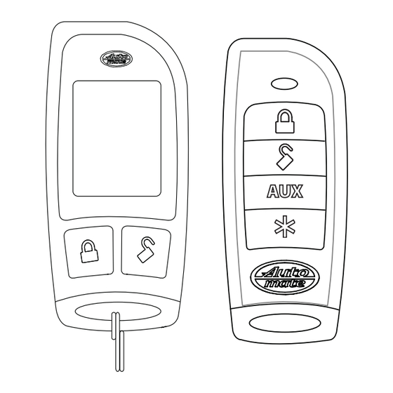
Responder LSC 2-Way Internal Antenna Display Function Button Command Mini-USB Port Buttons Feature Description Internal Antenna Used for transmitting and receiving information Display Status screen - the upper portion of the display contains status icons for the system, siren, alarm zones, and remote control Text field - the lower portion of display shows the clock, command confirmations, page messages and programming menus... - Page 9 Control Center Control Center Button Control Center The control center, typically located on the upper part of the front windshield sends and receives commands or messages to and from your system. It consists of: The In-vehicle system antenna, for 2 way communication. The control center LED, as a visual indicator of the system’s status.
-
Page 10: Status Screen Icons
Status Screen Icons Status Screen Icons Text Field The table below describes all the status screen icons. Icon Description Armed: The system is armed, the alarm is enabled Locked: The system is locked in valet, the alarm is disabled Disarmed: The system is disarmed, the alarm is disabled Unlocked: The system is unlocked in valet, the alarm is disabled Siren is disabled for sensor triggers;... - Page 11 Icon Description On during a sensor zone full trigger output On during fault report to indicate a sensor is active and bypassed when arming On during the door zone full trigger output On during fault report to indicate a door is open and bypassed when arming On during a hood zone full trigger output On during fault report to indicate the hood is open and...
- Page 12 Icon Description Text field Displays the clock, message text and feature menus Remote start is active, the engine is running (with optional remote start module only) * This icon not present until the car 2 is turned on in the Setup Remote configuration menu.
-
Page 13: Using Your System
Using your System Commands and Confirmations Commands, basic or advanced, are used to activate system fea- tures and are performed by pressing one of the command buttons. Basic commands control the most often used security features while advanced commands control more specialized features and request reports. -
Page 14: Responder Lsc Command Table
Responder LSC Command table Direct Access Level Button LEVEL 1 LEVEL 2 LEVEL 3 LEVEL 4 Arm/Lock Silent Arm Sensor Sensor Silent Full Silent (Panic) Bypass Disarm/Unlock Silent Disarm Remote Valet Car Finder Remote Start*/ Aux 1/4** Aux/Trunk AUX 1 AUX 2 AUX 3 AUX 4... -
Page 15: Basic Commands (Direct Access)
Basic Commands (Direct Access) Press and release 6:30 The alarm arms, doors lock (if connected), and the siren chirps and parking lights flash once. The text and beeps play ARMED to confirm and the system status icons update. If valet mode* is on, the doors lock and the text and tone play. -
Page 16: Aux/Trunk
AUX/Trunk Press and hold The trunk opens (if connected) when this button is pressed for 2 sec- onds. The text and tones play to confirm. TRUNK Remote Start /AUX 1/ AUX 4 Press and release Remote Start*** Activates (or if on, deactivates) an optional remote starter. The engine and parking lights turn on or off accordingly. -
Page 17: Advanced Commands: (Level 1)
Advanced Commands: (Level 1) Press and release the button one time, prior to pressing the following command buttons. level 1 Silent Arm Press and release The alarm arms, doors lock (if connected), and the parking lights flash once. The text plays to confirm and the system status SILENT ARMED icons update. -
Page 18: Advanced Commands: (Level 2)
Advanced Commands: (Level 2) Press and release the button two times, prior to pressing the following command buttons. level 2 Sensor Bypass Press and release Performing the sensor bypass command will incrementally bypass sen- sor operations and be confirmed as follows: Warn-away bypass: The parking lights flash 2 times, 1 beep and 1 fault tone play to confirm. -
Page 19: Advanced Commands: (Level 3)
Advanced Commands: (Level 3) Press and release the button three times, prior to pressing the following command buttons. level 3 Sensor Silent Arm* Press and release The alarm arms, doors lock, the siren chirps and parking lights flash 3 times. The text and beeps play to confirm and the SENSOR SILENT ARM system and siren status icons update. -
Page 20: Advanced Commands: (Level 4)
Advanced Commands: (Level 4) Press and release the button four times, prior to pressing the following command buttons. level 4 Full Silent Arm* Press and release The alarm arms, doors lock, and the siren chirps and parking lights flash 4 times. The text and beeps play to confirm FULL SILENT ARM and the system and siren icons update. -
Page 21: Responder Lsc Configuration
Responder LSC Configuration Operations of the Responder LSC and how it communicates messages are set in the configuration main menu. Navigating Menus and Options Navigating menus and features, changing options, and exiting are performed using the remote control buttons. The following instructions discuss how to access and configure the settings. -
Page 22: Main Menu
Main Menu The following main menu list of features is available for configuration of the remote control. Setup Remote Menu: Keypad Lock Options: AUTO When , the buttons do not lock and always perform a com- mand when pressed. When set to , the buttons lock after AUTO a 20 second lapse between buttons presses to prevent uninten-... -
Page 23: Remote Start Info
this period. Just press any button to resume system monitoring. When set to it wakes up every few seconds to listen for pages from the system. When set to it does not wake up to receive alarm trigger pages. Note: When , responses are still received when a command is performed but alarm trigger pages will not be received. -
Page 24: Car 2
Car 2 Options: HOME This remote can control two systems independently. When set to , the car 2 select option is not available. When set to the remote can be set to control 2 systems. The option is HOME for pairing to a home security system. BackLight Options: The status screen backlighting can be... -
Page 25: Clock Set
Selects the type of system, namely; security or remote keyless entry to which the remote has been paired, and adjusts the text and main menu accordingly. This has been pre-set by the factory for your system. Clock Set Options: HOUR The clock is formatted for 12 hour mode with AM or PM in- dicated. - Page 26 Prepare the system Open a door. Turn the ignition on. Press and release then press and hold the control center button. The control center LED flashes and the siren chirps one time to confirm the system is prepared. Release the control center button and proceed below. Note: Begin pairing within 60 seconds or the system will exit (indi- cated by a long siren chirp) and will need to be prepared again.
-
Page 27: Demo Mode
Demo Mode: Demo mode plays a pre-selected group of animations as a demonstra- tion tool to show friends or family. Running demo mode shortens the battery life over time if used excessively : The remote will display a selection of icons on SINGLE SILENT the status screen without beeps and tones then stop : The remote will display a selection of icons on... -
Page 28: Alarm Features
Alarm Features Normal Arm Protection Control center LED: The control center LED flashes as a visual indicator that your vehicle’s security system is active. Starter Kill: The failsafe starter kill relay prevents the engine from start- Note May require additional parts and installation Sensor triggers: The onboard shock sensor can distinguish minor im- pacts from major impacts to the vehicle exterior. -
Page 29: Full Silent Arm Protection
Full Silent Arm Protection Sensor warn-away, sensor full trigger and point of entry activations will only send messages to the remote, with parking light flash and siren outputs defeated. Sensor Warn-away Messages When the remote receives a sensor warn-away message it emits 10 beeps (if on) and displays a sensor zone specific text SENSOR WARN... -
Page 30: Trigger Zone Fault Report
Trigger Zone Fault Report When armed by remote command the system runs a status check of the alarm trigger zones. Faulty zones (usually caused by dome light delay or open trunk) are bypassed and reported via the control center LED and remote, while all other trigger zones remain active and are monitored to protect the vehicle. -
Page 31: Alarm Report When Requested
Table of Zones Zone # (led flashes) Zone Name Trunk Shock Sensor Door Sensor 2 Ignition Hood Sensor 3 Alarm Report when Requested The alarm report displays the two most recent alarm triggers depend- ing on the system state when requested. When disarmed, the report will display text to identify the two most recent triggers since the ve- hicle was last driven. -
Page 32: Remote And System Operations
Remote and System Operations Passive Arming* Park and exit the vehicle, after the doors are closed the passive arm- ing countdown begins. The control center LED flashes quickly and upon reaching 20 seconds the siren then chirps once. At 30 seconds the system arms itself. -
Page 33: Valet Mode
Valet Mode Valet mode can be entered and exited by performing the remote valet command or manually using the vehicle key and the control center button. When entered, the alarm functions are defeated while the convenience features still operate normally. Arm and disarm commands lock and unlock the doors while the text and beeps play to confirm. -
Page 34: Out Of Range
Out of Range Each time a command is performed the remote will expect a com- mand confirmation from the system. If a command confirmation is not received the out-of-range icon ( ) and a fault tone will play as an alert. -
Page 35: Vehicle Recovery System (Vrs)
Vehicle Recovery System (VRS) In case your vehicle is stolen or carjacked, VRS sounds the siren and flashes the parking lights to persuade the thief to abandon the vehicle, and when the ignition is turned off, activates the starter kill to prevent the engine from restarting. -
Page 36: 1-Way Companion Remote Control
1-way Companion Remote Control Transmit Command Buttons Press and Release Shift (Press/re- Press/Hold Action lease “AUX” first) for 2 secs. Button Silent Arm Arm and Panic Disarm Silent Disarm No function Shift* Sensor Bypass Trunk Release Remote Starter**/Auxil- No Function iary 1-4 activation*** Advanced commands are performed by pressing and releas- ing the AUX button prior to pressing a command button to... -
Page 37: Accessing Commands
Using the 1-way Companion remote This remote control performs a limited set of system commands as shown in the previous table. As a 1-way, it only transmits without providing feedback. Siren chirps and parking light flashes are used to indicate that a command has been received and activated as de- scribed in the Basic Commands and Advanced Commands sections. -
Page 38: Pairing A 1-Way Remote Control
Sensor Bypass At any time while the system is armed, press and release the AUX button on the remote and then within two seconds, press and hold the AUX button for one second to enable the sensor bypass mode. Repeating the previous steps incrementally bypass sensor operations and are confirmed as follows: Warn-away Bypass: The parking lights flash 2 times. - Page 39 Release the button. Press and hold the button until the transmit LED turns on solid. The siren emits one sound to confirm learning. Repeat for each remote control to be learned (up to four) Turn the ignition off or wait 60 seconds to exit learning, the siren emits 2 sounds to confirm.
-
Page 40: System Expansion Options
System Expansion Options Controlling Two Vehicles (car select) The Responder LSC can control systems in two different vehicles sav- ing the need for multiple remote controls. This feature also allows for customized system configurations on each vehicle that has more than one driver. - Page 41 style of driver priority unlocking for added security during disarming. Auxiliary Channels The auxiliary channel outputs of this system can activate many of the convenience features found in today’s vehicles. Once a command is performed to activate a convenience feature the Responder LSC displays text that matches the feature.
-
Page 42: Battery Information (Responder Lsc)
Battery Information (Responder LSC) The Responder LSC remote control is powered by an internal re- chargeable battery that can be serviced only through an authorized Directed Electronics dealer. The information and precautions in this section can help maximize your battery’s life and usage in providing your Responder LSC remote control with many years of trouble free operation. -
Page 43: Low Battery Alerts
be charged at the earliest opportunity or failure to control the system may occur. Low Battery Alerts When disarming the system using a remote control with a low battery (LSC or 1-way companion), the siren emits one additional chirp as an alert. -
Page 44: Battery Information (1-Way)
Battery Information (1-way) The 1- way companion remote control is powered by one 3V coin cell lithium battery (CR-2032), which can be purchased at most retailers that sell batteries. When the battery begins to weaken, the operating range is reduced (see “Low Battery Alerts” on page 40). Battery Replacement Unscrew the hardware on unit rear and remove from housing. -
Page 45: Glossary Of Terms
Glossary of Terms Document Terminology Control Module The “brain” of your system. Usually hidden underneath the dash area of the vehicle. It houses the microprocessor which monitors your vehicle and controls all of the system’s functions. Responder A hand-held, remote control which operates the various func- way Remote Control) tions of your system and receives messages and pages from the system. -
Page 46: Patent Information
Patent Information This product is covered by one or more of the following United States patents: Remote Start Patents: 5,349,931; 5,872,519; 5,914,667; 5,952,933; 5,945,936; 5,990,786; 6,028,372; 6,467,448; 6,561,151; 7,191,053; 7,483,783 Vehicle Security Patents: 5,467,070; 5,532,670; 5,534,845; 5,563,576; 5,646,591; 5,650,774; 5,673,017; 5,712,638; 5,872,519; 5,914,667; 5,952,933;... -
Page 47: Government Regulations
Government Regulations This device complies with Part 15 of FCC rules. Operation is subject to the fol- lowing two conditions: (1) This device may not cause harmful interference, and (2) This device must accept any interference received, including interference that may cause undesirable operation. This equipment has been tested and found to comply with the limits for a class B digital device, pursuant to Part 15 of the FCC Rules. -
Page 48: Additional Information
Additional information Interference All radio devices are subject to interference which could affect proper performance. Upgrades and Batteries Any upgrades to this product and/or installation of batteries must be performed by an authorized dealer. Do not attempt to perform any unauthorized modifications to this product. -
Page 49: Limited Lifetime Consumer Warranty
Limited lifetime consumer warranty Directed Electronics. (“Directed”) promises to the original purchaser to repair or replace (at Directed’s election) with a comparable reconditioned model any Directed unit (hereaf- ter the “unit”), excluding without limitation the siren, the remote transmitters, the associated sensors and accessories, which proves to be defective in workmanship or material under reasonable use during the lifetime of the vehicle provided the following conditions are met: the unit was purchased from an authorized Directed dealer, the unit was profession-... - Page 50 ANY CONSEQUENTIAL DAMAGES OF ANY KIND. IN THE EVENT OF A CLAIM OR A DISPUTE INVOLVING DIRECTED OR ITS SUBSIDIARY, THE VENUE SHALL BE SAN DIEGO COUNTY IN THE STATE OF CALIFORNIA. CALIFORNIA STATE LAWS AND APPLICABLE FEDERAL LAWS SHALL APPLY AND GOVERN THE DISPUTE. THE MAXIMUM RECOVERY UNDER ANY CLAIM AGAINST DIRECTED SHALL BE STRICTLY LIMITED TO THE AUTHORIZED DIRECTED DEALER’S PURCHASE PRICE OF THE UNIT.
Need help?
Do you have a question about the 3303A and is the answer not in the manual?
Questions and answers