
Related Manuals for Husqvarna Z4219


Summary of Contents for Husqvarna Z4219
- Page 1 Operator´s manual Z4218/968999281 Z4219/968999511 Z4824/968999512 Z5426/968999508 Please read the operator’s manual carefully and make sure you understand the instructions before using the machine. English...
-
Page 3: Table Of Contents
OPERATOR’S MANUAL Contents Contents...1 Introduction ...3 Congratulations...3 General ...3 Driving and Transport on Public Roads ...3 Towing ...3 Operating ...3 Good Service ...4 Manufacturing Number ...4 Symbols and Decals ...5 Safety Instructions...7 General Use...7 Personal Safety Equipment ...9 Driving on Slopes...9 Children...10 Utility Box ...10 Maintenance ...11... - Page 4 WARNING! Failure to follow cautious operating practices can result in serious injury to the operator or other persons. The owner must understand these instructions, and must allow only trained persons who understand these instructions to operate the mower. Each person operating the mower must be of sound mind and body and must not be under the influence of any mind altering substance.
-
Page 5: Introduction
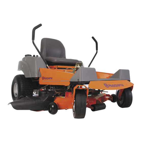
Introduction Congratulations Thank you for purchasing a Husqvarna ride-on mower. This machine is built for the greatest efficiency and rapid mowing primarily of large areas. Controls in one place and a hydrostatic transmission regulated by steering controls also contribute to the machine’s performance. -
Page 6: Good Service
Good Service Husqvarna’s products are sold all over the world and only in specialized retail stores with complete service. This ensures that you as a customer receive only the best support and service. Before the product is delivered, the machine has, for example, been inspected and adjusted by your retailer, see the certificate in the Service Journal in this operator’s manual. -
Page 7: Symbols And Decals
SYMBOLS AND DECALS Symbols and Decals These symbols are found on the machine and in the operator’s manual. Study them carefully so that you know what they mean. WARNING! Xxxxxxx xxxx xxxxxxxx xxx x Xxxxx xxxxxx xx. xx xxxxxxxx xxxxx xxx xx. Used in this publication to notify the reader of a risk of personal injury or death, particularly if the reader should neglect to follow instructions given in the manual. - Page 8 SYMBOLS AND DECALS Read Shut off engine Operators & remove key Manual before performing any maintenance or repair work. Whole Severing body of fingers exposure & toes. to thrown objects. Moving sharp blades under cover English- Keep a safe Use on distance from slopes no the machine.
-
Page 9: General Operation
SAFETY INSTRUCTIONS Safety Instructions These instructions are for your safety. Read them carefully. WARNING! This symbol means that important safety instructions need to be emphasized. It concerns your safety. IMPORTANT: THIS CUTTING MACHINE IS CAPABLE OF AMPUTATING HANDS AND FEET AND THROWING OBJECTS. - Page 10 SAFETY INSTRUCTIONS • Disengage blades when not mowing. Shut off engine and wait for all parts to come to a complete stop before cleaning the machine, removing the grass catcher, or unclogging the discharge guard. • Operate machine only in daylight or good artificial light.
-
Page 11: Personal Safety Equipment
SAFETY INSTRUCTIONS Personal Safety Equipment WARNING! When using the machine, approved personal protective equipment (shown in illustrations) shall be used. Personal protective equipment cannot eliminate the risk of injury but it will reduce the degree of injury if an accident does happen. -
Page 12: Children
SAFETY INSTRUCTIONS • Use extra care while operating machine with grass catchers or other attachments; they can affect the stability of the machine. Do not use on steep slopes. • Do not try to stabilize the machine by putting your foot on the ground. •... -
Page 13: Maintenance
SAFETY INSTRUCTIONS Maintenance WARNING! The engine must not be started when the driver’s floor plate or any protective plate for the mower deck’s drive belt is removed. Safe Handling of Gasoline To avoid personal injury or property damage, use extreme care in handling gasoline. Gasoline is extremely flammable and the vapors are explosive. - Page 14 SAFETY INSTRUCTIONS the sun may otherwise cause the fuel to expand and overflow. General Maintenance • Never operate machine in a closed area. • Keep all nuts and bolts tight to be sure the equipment is in safe working condition. •...
- Page 15 SAFETY INSTRUCTIONS • Acid in the eyes can cause blindness, contact a doctor immediately. • Be careful when servicing the battery. Explosive gases form in the battery. Never perform maintenance on the battery when smoking or near open flames or sparks. The battery can explode and cause serious injury/damage.
-
Page 16: Transport
SAFETY INSTRUCTIONS run over or into anything. If necessary, make repairs before starting. • Never make adjustments with the engine running. • The machine is tested and approved only with the equipment originally provided or recommended by the manufacturer. Only use approved repair parts for the machine. -
Page 17: Customer Responsibilities
(if any). If a spark arrester is used, it should be maintained in effective working order by the operator. A spark arrester for the muffler is available through your authorized Husqvarna dealer. English-... -
Page 18: Controls
Controls This operator’s manual describes the Husqvarna Zero Turn Rider. The rider is fitted with a Briggs and Stratton four-stroke engine developing 22-24 horse power. Transmission from the engine is made via two belt-driven hydrostat transaxles, one for each drive wheel. Using the left and right steering controls, the flow is regulated and thereby the direction and speed. -
Page 19: Controls
Recommended air pressure is 15 psi (1 bar). Tracking must be checked on a flat and level concrete or blacktop surface. If unit still does not track straight, contact a Husqvarna workshop for adjustment. CONTROLS Motion control levers WARNING! -
Page 20: Seat Adjustment Knobs
2. Seat adjustment knobs The seat can be adjusted lengthways. When making adjustments, loosen the four knobs under the seat pan, after which the seat can be moved backward or forward. Do not forget to tighten the knobs. 3. Fuses The fuses are located in the right front corner of the engine compartment. -
Page 21: By Pass Linkages
4. By pass linkages When pushing or pulling the mower, be sure to engage the IZT (Integraded Zeroturn Transaxle) bypass linkages. The IZT bypass linkages are located on the rear of the frame, below the rear engine guard. • Raise the deck into the highest cutting position. -
Page 22: Refueling
5. Refueling The machine has one fuel tank, just behind the seat. The tank capacity is 3 gallons (11.4 liters). The engine will run on a minimum of 85-octane unleaded gasoline (no oil mix). Environmentally adapted alkylate gasoline can be used. See also Technical Data concerning ethanol fuel. -
Page 23: Ignition Switch
7. Ignition Switch The ignition key is placed on the driver’s panel and is used to start and stop the engine. IMPORTANT INFORMATION Do not run the starter for more than five seconds each time. If the engine does not start, wait about 10 seconds before re- trying. -
Page 24: Hour Meter
10. Hour Meter The hour meter displays the total operating time. It will flash CHG OIL (Change Oil) at 50 hour intervals. The flash duration is one hour before and one hour after the interval. The CHG OIL icon will come on and shut off automatically. -
Page 25: Cutting Height Pedal
12. Cutting height pedal The deck cutting height is obtained by pressing the foot pedal forward to lift the deck. To lower the deck, you apply pressure to the top side of the foot pedal and allow it to pivot while allowing the lift arm to rotate to the rear of the unit. -
Page 26: Operation
Operation Read "Safety Instructions" section and following pages, if you are unfamiliar with the machine. Training Zero turn mowers are far more manueverable than typical riding mowers due to their unique steering capabilities. We suggest when first operating the mower, use a reduced throttle speed and reduced ground speed by NOT moving control levers to the furthest forward or reverse positions during initial operation, or until operator becomes comfortable with controls. -
Page 27: Before Starting
Before Starting • Read the sections Safety Instructions and Controls before starting the machine. • Perform the daily maintenance before starting (see Maintenance Schedule in the Maintenance section). • Check that there is sufficient fuel in the fuel tank. • Adjust the seat to the desired position. - Page 28 Disengage the mower blades by depressing the blade switch. Move the steering controls outward to the locked (outer) neutral position. Move the throttle to the middle position. If the engine is cold, the throttle control should be pushed forward to its choke position.
- Page 29 Press in and turn the ignition key to the start position. When the engine starts, immediately release the ignition key back to the run position. IMPORTANT INFORMATION Do not run the starter for more than 5 seconds each time. If the engine does not start, wait about 10 seconds before re-trying.
-
Page 30: To Start An Engine With A Weak Battery
To start an engine with a weak battery WARNING! Lead-acid batteries generate explosive gases. Keep sparks, flame and smoking materials away from batteries. Always wear eye protection when around batteries. If your battery is too weak to start the engine, it should be recharged. -
Page 31: Running
Running Release the parking brake by moving the lever downward. Your mower is equipped with an operator presence system. When the engine is running, any attempt by the operator to leave the seat without first setting the parking brake will shut off the engine. Move the steering controls to the neutral position (N). -
Page 32: Operating On Hills
Turning on the spot can be achieved by moving one control backward (behind the neutral position) and carefully moving the other steering control forward from its neutral position. Operating on hills Read the Safety Instructions "Driving on Slopes" in the "Safety Instructions". WARNING! Do not drive up or down hills with slopes greater than... -
Page 33: Mowing Tips
Mowing Tips • Observe and flag rocks and other fixed objects to avoid collisions. • Begin with a high cutting height and reduce it until the desired mowing result is attained. The average lawn should be cut to 2 1/2" (64 mm) during the cool season and over 3"... -
Page 34: Stopping The Engine
Stopping the Engine Allow the engine to idle a minute in order to attain normal operating temperature before stopping it, if it has been worked hard. Avoid idling the engine for longer periods, as there is a risk of the spark plugs fouling. Disengage the mower deck by depressing the blade switch. -
Page 35: Moving By Hand
Moving by Hand WARNING! No adjustments or maintenance to be carried out unless: - the engine stopped, - the ignition key has removed, - the parking brake is on. When pushing or pulling the mower, be sure to engage the IZT (Integraded Zeroturn Transaxle) bypass linkages. -
Page 36: Maintenance
Maintenance Maintenance Schedule The following is a list of maintenance procedures that must be performed on the machine. For those points not described in this manual, visit an authorized service workshop. An annual service carried out by an authorized service workshop is recommended to maintain your machine in the best possible condition and to ensure safe operation. - Page 37 Maintenance Check/adjust throttle cable Check the condition of belts, belt pulleys, etc. Change the engine oil Replace the engine oil filter Clean/replace the spark plugs Replace the air filter (paper filter) Check the caster wheels (every 200 hours) Clean the cooling fins Replace the air cleaner’s pre-filter Check/adjust the mower deck Check the engine valve clearance...
-
Page 38: Battery
Battery Your mower is equipped with a maintenance free battery and does not need servicing. However, periodic charging of the battery with an automotive type battery charger will extend its life. • Keep battery and terminals clean. • Keep battery bolts tight. •... -
Page 39: Ignition System
Ignition System The engine is equipped with an electronic ignition system. Only the spark plug requires maintenance. For recommended spark plug, see Technical Data. Remove the ignition cable boot and clean around the spark plug. Remove the spark plug with a spark plug socket wrench. -
Page 40: Checking The Safety System
Checking the Safety System The machine is equipped with a safety system that prevents starting or driving under the following conditions. The engine can only be started when: The mower deck is disengaged. The steering controls are in the outer, locked neutral position. -
Page 41: Checking The Engine's Cooling Air Intake
Checking the Engine's Cooling Air Intake Check that the engine’s cooling air intake is free from leaves, grass, and dirt. If the cooling air intake is clogged, engine cooling deteriorates, which can lead to engine damage. Checking and Adjusting the Throttle Cable Check that the engine responds to throttle increases and that a good engine speed is... -
Page 42: Replacing The Air Filter
Replacing the Air Filter If the engine seems weak or runs unevenly, the air filter may be clogged. If run with a dirty air filter, the spark plug can become fouled. For this reason, it is important to replace the air filter regularly (see the heading Maintenance Schedule for the proper service interval). -
Page 43: Replacing The Fuel Filter
Perform a stand still test and check that there is a braking action. To adjust the parking brake, contact the Husqvarna service workshop. WARNING! Faulty adjustment can cause an accident. -
Page 44: Checking The V-Belts
Checking the V-belts WARNING! No adjustments or maintenance to be carried out unless: • The engine is stopped. • The ignition key has been removed. • The parking brake is on. Deck belt V-belts are not adjustable. Replace belts if they begin to slip from wear. Deck belt removal WARNING! Idler arm is spring loaded. - Page 45 Deck belt installation NOTE: For ease in installing the deck belt, refer to the routing decal on bottom of seat. • Wrap the deck belt around the electric clutch pulley that is located on the engine shaft. • Route the belt forward between the EZT (E-Series Zeroturn Transaxles) and up onto the deck.
-
Page 46: Ezt Belt
EZT belt To replace EZT (E-Series Zeroturn Transaxle) belt Park the mower on a level surface. Engage the parking brake. EZT belt removal NOTE: Be careful not to damage the fan blades on the EZT´s as this can affect cooling or damage the EZT´s •... -
Page 47: Checking The Blades
Checking the Blades In order to attain the best mowing effect, it is important that the blades are well sharpened and not damaged. WARNING! Blades are sharp. Protect your hands with gloves and/or wrap blades with a heavy cloth when handling. -
Page 48: Adjusting The Mower Deck
Install and tighten blade bolt securely. Torque blade bolt to 27-35 ft/lb (35-45 Nm). IMPORTANT INFORMATION Special blade bolt is heat treated. Replace with a Husqvarna bolt if required. Do not use lower grade hardware than specified. Adjusting the Mower Deck WARNING! Before performing any service or adjustment checklist: 1. - Page 49 To level deck Adjust the deck while the mower is on a level surface. Make sure the tires are inflated to the correct pressure. See “Technical Data” under Transmission. If tires are under or over inflated, you can not properly adjust your deck.
- Page 50 Front-to-back adjustment IMPORTANT INFORMATION Deck must be leveled side-to-side, prior to leveling front to back. If the following front to back adjustment is required, be sure to adjust both front and rear linkages equally so the deck will stay level side to side. To obtain the best cutting performance, the deck should be adjusted so the front tip of the blades are approximately 1/8"...
- Page 51 To adjust anti-scalp rollers Deck has anti-scalp rollers. Anti-scalp rollers are properly adjusted when they are just slightly off of the ground when the deck is at the desired cutting height in the operating position. Anti-scalp rollers then keep the deck in the proper position to help prevent scalping in most terrain conditions.
-
Page 52: Cleaning And Washing
Cleaning and Washing Regular cleaning and washing, especially under the mower deck, will increase the machine’s lifespan. Make it a habit to clean the machine directly after use (after it is cooled), before the dirt sticks. Do not spray water on the top of the mower deck. -
Page 53: Lubrication
Lubrication Lubrication Schedule Lubrication schedule 12/12 Every year Lubricate with grease gun 1/52 Every Week 1/365 Every day General Remove the ignition key to prevent unintentional movements during lubrication. When lubricating with an oil can, it must be filled with engine oil. When lubricating with grease, unless otherwise stated, use a high grade molybdenum disulfide grease. -
Page 54: Lubricating The Cables
Lubricating the Cables If possible, grease both ends of the cables and move the controls to end stop positions when lubricating. Refit the rubber covers on the cables after lubrication. Cables with sheaths will bind if they are not lubricated regularly. If a cable binds, it can disrupt operation. If a cable binds, remove the cable and hang it vertically. - Page 55 Place the machine on a flat surface. Remove the yellow cap and fit a hose to the drain valve. Place a container under the engine where the hose from the oil drain valve exits. Remove the dipstick and open the drain valve by turning and pulling out the black sleeve.
- Page 56 Checking the oil level Check the oil level in the engine when the machine is standing level and the engine is stopped. Remove the dipstick, wipe it clean, and then replace it. The dipstick should be screwed into place. Take the dipstick out again and read the oil level.
- Page 57 The oil filter holds 0.1 liters of oil. Transmission The transmission is maintenance free. There is no need for level checks or oil changes. If a leak occurs, replace the unit or contact your Husqvarna dealer. LUBRICATION Changing the oil filter Kohler 8011-739 English-...
-
Page 58: Trouble Shooting Guide
TROUBLE SHOOTING GUIDE Trouble Shooting Guide Problem The engine will not start. The starter motor does not turn the engine over. The engine runs rough. English- Cause • The blade switch is engaged. • The steering controls are not locked in the neutral position. - Page 59 TROUBLE SHOOTING GUIDE The engine seems weak. The engine overheats. Battery not charging. The machine moves slowly, unevenly, or not at all. Mower deck not engaging. • Wrong fuel type. • Water in the fuel. • Clogged air filter. • Clogged air filter.
- Page 60 TROUBLE SHOOTING GUIDE Uneven mowing results. The machine vibrates. English- • Different air pressure in the tires on the left and right sides. • Bent blades. • The suspending for the mower deck is uneven. • The blades are blunt. •...
-
Page 61: Storage
Service When ordering spare parts, please specify the purchase year, model, type, and serial number. Always use genuine Husqvarna spare parts. An annual check-up at an authorized service workshop is a good way to ensure that your machine performs its best the following season. -
Page 62: Wiring Diagram
WIRING DIAGRAMS Wiring diagram 6. Seat unoccupied 8. Blade switch in OFF position 11. Brake switch OFF pos. 14-15. Motion control levers OUT 1. Battery 2. Accessory outlet 3. Key switch 4. To engine pigtail 5. Hour meter 6. Seat switch 7. -
Page 63: Technical Data
Rear tires, Turf pneumatic 18x9.5-8 Tire pressure, front and rear 15 PSI / 103 kPa / 1 bar TECHNICAL DATA Z4218 Z4219 Briggs and Stratton Intek Single 19 hp / 14.2kW Pressure with oil filter 1.5 qt / 1.4 liter 1.6 qt / 1.5 liter... - Page 64 Overall width, Chute up 43” / 109 cm Overall width, Chute down 52” / 132 cm English- TECHNICAL DATA Z4218 Z4219 42” / 107cm 1.5”- 4” / 3.8 - 10.2 cm 21” / 533 mm Standard Standard 85 ft/lb Warner 12 gauge, stamped steel 2.6 acres /h 10530 m...
- Page 65 Engine Manufacturer Briggs and Stratton Type Intek single Power 24 hp / 17.65kW Lubrication Oil capacity excl filter 1.5 qt / 1.4 liter Oil capacity incl filter 1.6 qt / 1.5 liter Engine oil SAE 5W30, 10W30 Synt. (See viscocity digram) SAE 30 Mineral API SF-SJ Fuel...
- Page 66 Equipment Cutting width 48” / 122cm Cutting height 1.5”- 4” / 3.8 - 10.2 cm Uncut circle Number of blades Blade length 16 1/2” / 419mm Nose rollers Sprung standard seat Standard Hinged armrests Hour meter Standard Blade engagement 85 ft/lb Warner Deck construction 12 gauge, stamped steel Productivity...
-
Page 67: Accessories
Accessories Head lights BioClip attachment (Mulch clip) Collection system Torque Specifications ·Engine crankshaft bolt ·Deck pulley bolts ·Lug nuts ·Blade bolt ·Standard ¼” fasteners ·Standard 5/16” fasteners ·Standard 3/8” fasteners ·Standard 7/16” fasteners ·Standard ½” fasteners When this product is worn out and no longer used, it shall be returned to the reseller or other party for recycling. -
Page 68: Conformity Certificates
CONFORMITY CERTIFICATES Conformity Certificates USA requirements Labels are placed on the engine and/or in the engine compartment stating that the machine will fulfill the requirements. This is also applicable to special requirements for any of the states, (Californian emission rules etc.). Do not remove any of these labels. Certificates can also be supplied with the machine at delivery or written in the Engine manual. -
Page 69: Service Journal
Service Journal Action Delivery Service 1. Charge the battery. 2. Adjust the tire pressure of all wheels to 1 bar (15 PSI). 3. Mount the steering controls in the normal position. 4. Connect the to the cables for the seat’s safety switch. -
Page 70: After The First 5-8 Hours
SERVICE JOURNAL After the First 5-8 Hours 1. Change engine oil. English-... -
Page 71: 25-Hour Service
SERVICE JOURNAL Action Date, mtr reading, stamp, sign 25-Hour Service 1. Sharpen/Replace mower blades if required. 2. Lubricate the caster wheels. 3. Check the tire pressures. 4. Check battery with cables. 5. Check/clean the engine’s cooling air intake. 6. Clean the air cleaner’s pre-filter (foam). English-... -
Page 72: 50-Hour Service
SERVICE JOURNAL Action Date, mtr reading, stamp, sign 50-Hour Service 1. Perform the 25-hour service. 2. Clean/replace the air cleaner’s filter cartridge (paper filter) (shorter intervals for dusty operating conditions). 3. Change the engine oil. 4. Inspect muffler/spark arrester. 5. Check/adjust the parking brake. English-... -
Page 73: 100-Hour Service
SERVICE JOURNAL Action Date, mtr reading, stamp, sign 100-Hour Service 1. Perform the 25-hour service. 2. Perform the 50-hour service. 3. Change the engine oil filter. 4. Clean/replace the spark plug. 5. Clean the cooling fins on the engine and transmission. 6. -
Page 74: 300-Hour Service
SERVICE JOURNAL Action Date, mtr reading, stamp, sign 300-Hour Service 1. Inspect the machine. Come to agreement with the customer as to which additional work is to be carried out. 2. Perform the 25-hour service. 3. Perform the 50-hour service. 4. -
Page 75: At Least Once Each Year
SERVICE JOURNAL Action Date, mtr reading, stamp, sign At Least Once Each Year 1. Clean the engine’s cooling air intake (25 hours). 2. Replace the air cleaner’s pre-filter (Oil-foam) (300 hours). 3. Replace the air filter’s paper cartridge. 4. Change the engine oil (50 hours). 5. - Page 76 SERVICE JOURNAL Action Date, mtr reading, stamp, sign English-...
- Page 77 SERVICE JOURNAL Action Date, mtr reading, stamp, sign English-...
- Page 78 SERVICE JOURNAL Action Date, mtr reading, stamp, sign English-...
- Page 80 113926Rir 06/05/06...
Need help?
Do you have a question about the Z4219 and is the answer not in the manual?
Questions and answers