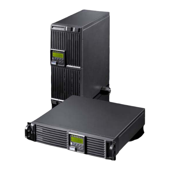
Rittal PMC 12 Assembly And Operation Instructions Manual
Ups system power modular concept
Hide thumbs
Also See for PMC 12:
- Oweners manual (28 pages) ,
- User manual (32 pages) ,
- Instruction manual (28 pages)

Subscribe to Our Youtube Channel
Related Manuals for Rittal PMC 12


Summary of Contents for Rittal PMC 12
- Page 1 UPS System Power Modular 7857.430 7857.431 Concept 7857.432 7857.482 PMC 12 7857.483 1, 2 and 3kVA PMC12 compact 2 and 3kVA Assembly and Operation Instructions...
- Page 2 Microsoft Windows is a registered trademark of Microsoft Corporation. Acrobat Reader is a registered trademark of Adobe Systems Incorporated.
-
Page 3: Table Of Contents
Important Safety Instruction 5.1. UPS S ....21 YSTEM LOCK IAGRAM 5.2....... 21 AINS IS VAILABLE Table of Contents 5.3......22 AINS IS BSENT 5.4......22 VERLOAD ONDITION 5.5........22 1. IMPORTANT SAFETY INSTRUCTION NVERTER AILURE 5.5.1. -
Page 4: Important Safety Instruction
3. Do not open the case, as there are no Rittal cannot accept any liability for damage serviceable parts inside. Your warranty and operational malfunctions that result from will be void. -
Page 5: S Torage I Nstructions
1.5. Proper This UPS is designed for providing power to IT systems. A use different from that described here is considered to be an improper use. Rittal cannot accept any liability for damage resulting from the improper use or the non-observance of this guide. -
Page 6: Product Introduction
Product Introduction the UPS to integrate even in the most difficult of 2. Product Introduction environments with space constraints. 2.1. General Characteristics This UPS is equipped with fully digitalised control logic for greater functionality and True online technology continuously supplies enhanced high level of power protection. -
Page 7: Ups Functional Descriptions
UPS Functional Descriptions 3.1.1. Symbols on the LCD Display Panel 3. UPS Functional Descriptions 3.1. UPS Front Panel Display Item Symbol Description Utility or Bypass LINE Source Battery Low Battery Abnormal UPS Overloading Site Wiring Fault Working Service Mode UPS Shutoff UPS Abnormal FAIL Lock... -
Page 8: R Ear P Anel D Escription Pmc12
UPS Functional Descriptions 3.2. Rear Panel Description PMC12 230V 1KVA 2KVA 3KVA USB Port RS232 Port Emergency Power Off (EPO) Dry Contact Signal inputs Communication Card Options Slot External Battery Connector AC power connection socket AC Outlets Two programmable outlets Utility Input fuse holder 10. -
Page 9: Rear
UPS Functional Descriptions 3.3. Rear Panel Description PMC12 compact 2KVA 12 11 3KVA 1. USB Port 2. RS232 Port 3. Emergency Power Off (EPO) Dry Contact Signal inputs 4. Communication Card Options Slot 5. External Battery Connector 6. AC power connection socket 7. -
Page 10: System Configuration
To save the settings press “OK”. To activate the configuration you have to restart the UPS- 3.4. Operating Modes & UPS System. Configuration Install the “Rittal PMC12 UPS-Software“ from 3.4.2. Using the Software the enclosed CD or download it from 1. Run the program „UPSMonitor“ http://www.rimatrix5.com/service_support/downloads.asp. -
Page 11: Port Explanation
UPS Functional Descriptions Turn outlet OFF when battery lower …% - select this option to automatically disable the outlet at the specified remaining battery power capacity(%) during battery mode to shed the less critical loads to prolong battery back-up time for the other more critical loads connected to the UPS. -
Page 12: Installation And Operation
Installation and Operation 4. Installation and Operation 3.5.1. True RS232 Port Descriptions The RS232 interface shall be set as follows: Warning! Read the Safety Instruction guide Baud Rate 2400 bps (page 5 to 6) before installing the Data Length 8 bits UPS! Stop Bit 1 bit... -
Page 13: Set Up
Installation and Operation 5. This UPS is not designed for outdoor use. 4.3. Set up 4.3.1. Tower Configuration Setup 4.3.2. Power Module + Battery Module Step 1 Relative humidity 30%~90% (non condensation) Note! The recommended temperature Step 2 range for the batteries is between 20 and 30°C. -
Page 14: Rack-Mount Configuration Setup
Installation and Operation Step 3 4.3.3. Rack-Mount Configuration Setup Step 1 Step 2 Step 4 UPS-Manual... -
Page 15: Operation
Installation and Operation 4.4. Operation 4.4.1. Start Up In Normal Mode 1. Make sure the voltage of Utility matches with the input voltage window of the UPS. 2. Connect the UPS to the wall Receptacle of drawing D the Utility. Turn on the UPS “ON” switch to start up the UPS. -
Page 16: Check Measured Values & Figures Detected By Ups
Installation and Operation must be completely restarted to get back to Normal Mode. drawing M drawing H 4.4.3. Check Measured Values & Figures detected by UPS drawing N If you would like to check the measured values & messages, please use scroll up and scroll down key pads. - Page 17 Installation and Operation Frequency Synchronized Window) drawing (Inverter Output Voltage) drawing U1(UPS Operation Mode) drawing V(Output Voltage Fine Tuning). drawing U1 drawing Q1 drawing U2 drawing Q2 drawing U3 drawing R1 drawing V drawing R2 drawing S drawing T UPS-Manual...
-
Page 18: Ups Default Settings And Their Alternatives
Installation and Operation 3. Press scroll up key pad, you may exe- drawing X. All those changes will be acti- cute special functions. The functions include vated only when the UPS is re-turned on. Buzzer ON (as drawing Q1) or buzzer OFF The LCD screen will be back to the original (as drawing Q2, Alarm silence for UPS screen before setting. -
Page 19: Shut Off
Installation and Operation (b) Check to see Chapter 6.1 to trouble Buzzer Beep shoot the problem of the UPS; otherwise, Status Definitions Descriptions consult your local distributor for service. (c) Press key pad for 5 seconds and UPS faulty, Inverter buzzer will sound twice. -
Page 20: Replacement
Installation and Operation 4.6. Battery Replacement PMC12 Step 4 Step 1 1KVA Step 2 2K/3KVA Note! Was the used battery of the UPS System removed during normal operation this will not immediately be recognized by the PMC12 Step 3 because after the startup the UPS will check only sporadically (approx. - Page 21 Installation and Operation Step 4: 4.7. Battery Replacement PMC12 compact Step 1: Note! Was the used battery of the UPS System removed during normal operation this will not immediately be recognized by the PMC12 because after the startup the UPS will check only sporadically (approx.
-
Page 22: Ups Working Principle
UPS Working Principle Paragraph 5.2 ~ 5.7 below provide detailed de- 5. UPS Working Principle scriptions of the UPS operating principle. 5.1. UPS System Block Diagram 5.2. When Mains is Available When Mains is available, the AC source is rec- tified to DC, partially fed into the charger to charge battery and partially fed into inverter. -
Page 23: When Mains Is Available 5.3. When Mains Is Absent 5.4. Overload Condition
UPS Working Principle 5.3. When Mains is Absent The working principle of the UPS under Mains absent condition is illustrated as follows: 1. When Mains absent, the UPS will direct the battery energy automatically to the Inverter without delay, and turn off the charger and AC/DC converter. -
Page 24: Inverter/Internal Over Temperature 23 5.5.3. Inverter Over-Current And Inverter Output Voltage Out Of Tolerance
Maintenance Guide 6. Maintenance Guide 5.5.2. Inverter/Internal Over temperature 6.1. Trouble Shooting If the UPS experiences internal over-tempera- ture when Utility is normal, it will switch to by- When the UPS becomes faulty or malfunctions pass loop. The UPS will switch back to inverter during operation, you may check the fault lists mode when the over-temperature situation is below for respective solutions. - Page 25 Allow the battery to recharge if the batter is weak. If problem persist UPS is unable to after recharging, provide backup replace the power source battery. If problem persist, consult your local dealer, Rittal or customer service for technical assistance. UPS-Manual...
-
Page 26: E Rror C Odes And Their D Escriptions
Bypass overload Note! Does the PMC12 show an Error Code that is not described in the above table please contact the Rittal Service. 6.3. Maintenance Clean the dust from the ventilation openings and intakes on the rear panel. 1. Turn off the UPS and wipe the casing with a damp cloth. -
Page 27: Snmp Adapter
RCCMD send function, for an automatic net- http://www.rimatrix5.com work wide shut down or just for informing con- E-mail: info@rittal.de nected users. The shut down procedure can be initiated on a low residual battery autonomy time (downtime) or by a countdown timer which is started at the beginning of the alarm. -
Page 28: Technical Specifications
Technical Specifications Technical Specifications Model 1KVA 2KVA 3KVA VA Rating Apparent Output Power 1000VA 2000VA 3000VA 800 Watts 1600 Watts 2400 Watts Active Output Power Power Factor Topology Double conversion On-Line Type Rack/Tower Agency Approvals 230V Models: CE Input Voltage Window 230V 120/140/160 - 288Vac Base on load percentage (0~33/33~66/66~100%) - Page 29 Technical Specifications Harmonic 3% THD(Linear Load) Distortion 7% THD(Non-Linear Load) Transient Efficiency 60ms/5% Response(ms) Waveform Pure Sine wave To AC Mode (Full load) Efficiency To Battery Mode (Full load) Model 1KVA 2KVA 3KVA Battery System Type 12V/7,2Ah 12V/7,2Ah 12V/9Ah Numbers of Batteries Backup Time(100%) >7min.
- Page 30 Technical Specifications Protection (AC Mode ) <105% continuous >106% ~ 120% for 30 seconds transfer to bypass >121% ~ 150% for 10 seconds transfer to bypass >150% for immediately transfer to bypass Buzzer continuously alarms. (Battery Mode) <105% continuous >106% ~ 120% for 30 seconds shuts down >121% ~ 150% for 10 seconds shuts down >150% for immediately shuts down...
- Page 31 Technical Specifications Environmental Operation Temperature* 0 - 40 °C Noise Level < 50 dBA Relative Humidity 0 to 90% (Without condensation) Interface Interface Type 1x USB port, 1x RS-232 port, 1x Slot for Communication Card SNMP Power management from SNMP manager and Web browser Compatible platforms Windows 95/98/NT/2000/XP/Vista, Novell NetWare, Linux, etc.
- Page 32 Technical Specifications This side is intentionally empty. UPS-Manual...
- Page 33 Rittal GmbH & Co. KG · Postfach 1662 · D-35726 Herborn Telefon +49(0)2772 505-0 · Telefax +49(0)2772 505-2319 · eMail: info@rittal.de · www.rittal.de...
Need help?
Do you have a question about the PMC 12 and is the answer not in the manual?
Questions and answers