Rittal PMC12 Oweners Manual
1phase double conversion true online ups system 1 - 3kva
Hide thumbs
Also See for PMC12:
- Assembly and operation instructions manual (33 pages) ,
- User manual (32 pages) ,
- Instruction manual (28 pages)
Table of Contents
Advertisement
Rittal PMC12
UPS-Manual
7857.430
7857.431
7857.432
1phase double conversion
true online UPS System
1 - 3kVA
FRIDHELM L O H GROUP
R i t t a l GmbH & Co. KG
Auf dem Stützelberg
D – 3 5 7 4 5 H e r b o r n
Deutschland
Germany
Email: Info@rittal.de
http://www.rittal.com
Service -Tel. : (+49) - (0)2772 / 505 - 0
Service - Fax : (+49) - (0)2772 / 505 - 2319
A 38333 03 IT 74e.doc
Advertisement
Table of Contents

Subscribe to Our Youtube Channel
Related Manuals for Rittal PMC12


Summary of Contents for Rittal PMC12
- Page 1 D – 3 5 7 4 5 H e r b o r n Deutschland Germany Email: Info@rittal.de http://www.rittal.com Service -Tel. : (+49) - (0)2772 / 505 - 0 Service - Fax : (+49) - (0)2772 / 505 - 2319 Rittal PMC12 UPS-Manual 7857.430 7857.431 7857.432 1phase double conversion true online UPS System...
-
Page 2: Important Safety Instruction
Important Safety Instruction Microsoft Windows is a registered trademark of Microsoft Corporation. Acrobat Reader is a registered trademark of Adobe Systems Incorporated. UPS-Manual... -
Page 3: Table Of Contents
Important Safety Instruction 5.3......19 AINS IS BSENT 5.4......19 VERLOAD ONDITION Table of Contents 5.5........19 NVERTER AILURE 5.5.1. Output Load short circuit when supply via inverter ..........19 IMPORTANT SAFETY 5.5.2. Inverter/Internal Over temperature.20 INSTRUCTION ..........4 5.5.3. Inverter Over-current and Inverter Output Voltage Out of tolerance.....20 1.1. -
Page 4: Important Safety Instruction
PMC12 UPS-System. 4. If liquids are split onto the UPS or for- You should read this operating guide prior to... -
Page 5: Storage Instruction
Important Safety Instruction 15. Observe the valid regulations for the electrical installation for the country in which the unit is installed and operated, and the national regulations for accident prevention. Also observe any company- internal regulations (work, operating and safety regulations). 16. -
Page 6: Product Introduction
Should the output becomes short-circuited, A use different from that described here is the UPS puts the system on stand-by considered to be an improper use. Rittal mode, provide visual & audible alarm, and cannot accept any liability for damage re-... -
Page 7: Ups Functional Descriptions
UPS Functional Descriptions 3.1.1. Symbols on the LCD Display Panel 3. UPS Functional Descriptions 3.1. UPS Front Panel Display Item Symbol Description Utility or Bypass LINE Source Battery Low Battery Abnormal UPS Overloading Site Wiring Fault Working Service Mode UPS Shutoff UPS Abnormal FAIL Lock... -
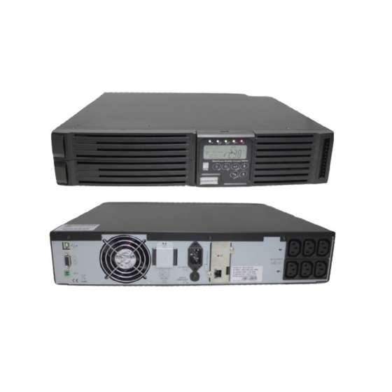
Page 8: Rear Panel Descriptions
UPS Functional Descriptions 3.2. Rear Panel Descriptions 230V 1KVA 2KVA 3KVA USB Port RS232 Port Emergency Power Off (EPO) Dry Contact Signal inputs Communication Card Options Slot External Battery Connector AC power connection socket AC Outlets Two programmable outlets Utility Input fuse holder 10. -
Page 9: Operating Modes
UPS Functional Descriptions **Sensitivity Low : 184~260V, 3.3. Operating Modes & Voltage System High: 194~260V Configurations Download from 3.3.2. Programmable Outlet Setting www.rimatrix5.com/dl_power.htm the “Setting The UPS is equipped with 2 programmable Tool” and open the Software to see the screen outlets for use to supply to less critical loads. -
Page 10: Communication Porte
UPS Functional Descriptions Outlet Turn Off When Battery Lower than 3.4.1. True RS232 Port Descriptions - select this option to automatically disable The RS232 interface shall be set as follows: the outlet at the specified remaining battery power capacity(%) during battery mode to Baud Rate 2400 bps shed the less critical loads to prolong battery... -
Page 11: Installation And Operation
Installation and Operation 4. Installation and Operation Warning! Read the Safety Instruction guide (page 5 to 6) before installing the UPS! 4.1. Unpacking Inspect the UPS upon receipt. The manufac- turer designed robust packaging for your prod- uct. However, accidents and damage may oc- cur during shipment. -
Page 12: Power Module + Battery Module
Installation and Operation 4.3.2. Power Module + Battery Module Step 2 Step 1 Step 3 Step 2 Step 4 4.3.3. Rack-Mount Configuration Setup Step 1 UPS-Manual... -
Page 13: Operation
Installation and Operation 4.4. Operation 4.4.1. Start Up In Normal Mode 1. Make sure the voltage of Utility matches with the input voltage window of the UPS. 2. Connect the UPS to the wall Receptacle of the Utility. Turn on the UPS “ON” switch to drawing D start up the UPS. -
Page 14: Check Measured Values & Figures Detected By Ups
Installation and Operation drawing L drawing H drawing M drawing I 4.4.3. Check Measured Values & Figures detected by UPS If you would like to check the measured values & messages, please use scroll up and scroll down key pads. When you use scroll down drawing N key pad, the LCD display will illustrate in se- quence from drawing E(Input Voltage) - Page 15 Installation and Operation drawing P2 drawing S 2. Press key pad to scroll down the LCD screen, then check the UPS settings. The LCD display will show in sequence: drawing P1(buzzer) drawing Q1(self test) drawing R1(Bypass Voltage) drawing S(Output Fre- quency Synchronized Window) drawing T (Inverter Output Voltage) drawing U1(UPS Operation Mode) drawing V(Output Voltage...
-
Page 16: Ups Default Settings And Their Alternatives
Installation and Operation 3. Press scroll up key pad, you may exe- vated only when the UPS is re-turned on. cute special functions. The functions include The LCD screen will be back to the original Buzzer ON (as drawing Q1) or buzzer OFF screen before setting. -
Page 17: Shut Off
Installation and Operation (d) Turn off the Breaker of the Utility Input. 4.6. Battery Replacement (e) The UPS lock problem is solved now. Step 1 4.4.7. Shut Off 1. Press key pad for about 5 seconds, the Inverter output will be turned off, then the output load is supplied by Bypass loop and the LCD screen shows as Drawing B. -
Page 18: Ups Working Principle
UPS Working Principle Step 4 The table below provide a summery guide to 1KVA the UPS operating modes against the Utility AC Power Source conditions. Utility UPS Operating LEDs Conditions Modes Display indications Rectifier convert AC to DC, battery charging, Inverter convert DC to Mains Available LEDs remain... -
Page 19: Hen Mains Is Absent
UPS Working Principle by the inrush produce by the loads, the UPS 5.3. When Mains is Absent is equipped with electronics overload protec- tion feature as standard. If the UPS loading is The working principle of the UPS under Mains absent condition is illustrated as follows: >105~120% of its capacity, it will switch to bypass mode in 30 seconds to protect the In-... -
Page 20: Inverter/Internal Over Temperature
Maintenance Guide 6. Maintenance Guide 5.5.2. Inverter/Internal Over temperature 6.1. Trouble Shooting If the UPS experiences internal over-tempera- ture when Utility is normal, it will switch to by- When the UPS becomes faulty or malfunctions pass loop. The UPS will switch back to inverter during operation, you may check the fault lists mode when the over-temperature situation is below for respective solutions. -
Page 21: Rror Codes And Their Descriptions
If problem persist after recharging, replace the battery. If problem persist, consult your local dealer, Rittal or customer service for technical assistance. Note! When the Fault LED illuminated, the error code is shown in the LCD display. Check the error code. -
Page 22: Bundle Software Installation Guide
Bundle Software Installation Guide consistent for the whole parallel system - or 7. Bundle Software Installation specific values from the single modules. Guide External SNMP-Adapter 7.1. Hardware Installation 1. Connect the male connector of RS232/USB cable to the UPS communication port. Ethernet 2. -
Page 23: Customer Service
Systems, analogous to PMC-Software. Our SNMP Interfaces are compatible to RCCMD. 9. Customer Service If you have any technical questions or ques- tions concerning our product spectrum, contact the following service address: Tel.: +49 (0)2772/505-1855 http://www.rimatrix5.com E-mail: info@rittal.de UPS-Manual... - Page 24 Technical Informations Technical Informations Model 1KVA 2KVA 3KVA VA Rating Apparent Output Power 1000VA 2000VA 3000VA Active Output Power 700Watts 1400Watts 2100Watts Power Factor Topology Double conversion On-Line Type Rack/Tower Agency Approvals 230V Models: CE Input Voltage Window 230V 120/140/160 - 288Vac Base on load percentage (0~33/33~66/66~100%) Low Line 230V...
-
Page 25: Battery System
Technical Informations Model 1KVA 2KVA 3KVA Battery System Type 12V/7,2Ah 12V/7,2Ah 12V/9Ah Numbers of Batteries Backup Time(20%) >66min. >66min. >59min. Backup Time(40%) >27min. >28min. >19min. Backup Time(60%) >14min. >14min. >12min. Backup Time(80%) >10min. >10min. >8min. Backup Time(100%) >7min. >7min. >5min. Recharging Time 4 Hours to 90% Charging Current (Max.) -
Page 26: Audible Alarm
Technical Informations Model 1KVA 2KVA 3KVA (Bypass Mode) <105% continuous >106% ~ 120% for 250 seconds shuts down 121% ~ 130% for 125 seconds shuts down > >131% ~ 135% for 50 seconds shuts down >136% ~ 145% for 20 seconds shuts down >146% ~ 148% for 5 seconds shuts down >149% ~ 157% for 2 seconds shuts down >158% ~ 176% for 1 seconds shuts down... - Page 27 Technical Informations Model 1KVA 2KVA 3KVA Backup Time with Extended Battery Module Load 100% >66min. >34min. >30min. >90min. >52min. >46min. 1 extended Battery module >120min. >69min. >60min. >180min. >109min. >95min. >350min. >210min. >180min. Load 100% >130min. >66min. >60min. >160min. >90min. >75min.
- Page 28 Technical Informations UPS-Manual...
Need help?
Do you have a question about the PMC12 and is the answer not in the manual?
Questions and answers