Table of Contents
Advertisement
Featuring the
WARNING:
If the information in these instructions is not followed exactly, a fire or
explosion may result causing property damage, personal injury or loss of life.
-
Do not store or use gasoline or other flammable vapors and liquids in the vicinity of this or any
other appliance.
WHAT TO DO IF YOU SMELL GAS
• Do not try to light any appliance.
• Do not touch any electrical switch; do not use any phone in your building.
• Immediately call gas supplier from a neighbor's phone. Follow the gas supplier's instructions.
• If you cannot reach your gas supplier, call the fire department.
-
Inst allat ion and service must be performed by a qualified inst aller, service agency or t he gas
supplier.
This appliance may be installed as an OEM installation in a manufactured (mobile) home and
must be installed in accordance with the manufacturer's instructions and the manufactured home
construction and safety standard, Title 24 CFR, Part 3280.
This appliance is only for use with the type(s) of gas indicated on the rating plate. A
conversion kit is supplied with the appliance.
Sturbridge Owner's Manual
Installer: After installation give this manual to the home-
owner and explain operation of this heater.
Copyright 2003, T.I.
$10.00
Burner
Part # 100-01142
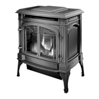
• Direct Vent Freestanding Stove
• Natural Gas or Propane
• Vent Horizontally or Vertically
• Standard Residential
• Mobile Home Approved
Tested and Listed by
OMNI-Test Laboratories, Inc.
Beaverton, Oregon
Report # 028–S–50-5
ANSI Z21.88
10850 117th Place N.E. Kirkland, WA 98033
Advertisement
Table of Contents

Subscribe to Our Youtube Channel
Related Manuals for Lopi Sturbridge


Summary of Contents for Lopi Sturbridge
- Page 1 This appliance is only for use with the type(s) of gas indicated on the rating plate. A conversion kit is supplied with the appliance. Sturbridge Owner’s Manual Installer: After installation give this manual to the home- owner and explain operation of this heater.
-
Page 2: Introduction & Important Information
Introduction Introduction We welcome you as a new owner of a Lopi Sturbridge stove. In purchasing a Sturbridge you have joined the growing ranks of concerned individuals whose selection of an energy system reflects both a concern for the environment and aesthetics. The Sturbridge is one of the finest home heaters the world over. -
Page 3: Table Of Contents
Air Shutter Adjustment (if necessary)....17 Interior Masonry Chimney Conversion ....39 Check Flame ..........18 Index Glass Removal (& installation) ......19 Index............40 Log Installation..........20 Travis Industries 1 0 0 - 0 1 1 4 2 4 0 2 0 9 1 7... -
Page 4: Safety Precautions
Travis Industries 1 0 0 - 0 1 1 4 2 4 0 2 0 9 1 7... - Page 5 Always follow the instructions in this manual. • If the fiber logs become damaged, replace with Travis Industries log set. • Plug the heater into a • Do not touch the hot 120V grounded electrical surfaces of the heater.
-
Page 6: Specifications
This heater is shipped in natural gas (NG) configuration but may be converted to propane (LP) using the included LP conversion kit. The sticker on top of the gas control valve will verify the correct fuel. Travis Industries 1 0 0 - 0 1 1 4 2... -
Page 7: Installation
Door Latch Tool (to un-latch glass frame) • Touch-Up Paint Installation Overview See "Vent Requirements" "Clearances" See "Gas Line Installation" See "Floor Protection Requirements" Travis Industries 1 0 0 - 0 1 1 4 2 4 0 2 0 9 1 7... -
Page 8: Installation Hints
When the optional blower is installed it must be connected to a properly grounded three-prong receptacle. Do not cut or remove the grounding prong from the optional blower cord. Travis Industries 1 0 0 - 0 1 1 4 2... -
Page 9: Heater Placement Requirements
(they dampen any noise that may transmit through the hearth). Do not adjust with weight on the legs, the rubber tips may tear. Travis Industries 1 0 0 - 0 1 1 4 2 4 0 2 0 9 1 7... -
Page 10: Gas Line Installation
Standard Input Pressure Natural Gas 7” W.C. (1.74 Kpa) Pr o p an e 13” W.C. (3.23 Kpa) Travis Industries 1 0 0 - 0 1 1 4 2 4 0 2 0 9 1 7... -
Page 11: Vent Requirements
Horizontal sections require a 1/4" rise every 12" of travel • Horizontal sections require non-combustible support every three feet (e.g.: plumbing tape) Travis Industries 1 0 0 - 0 1 1 4 2 4 0 2 0 9 1 7... -
Page 12: Approved Vent Configurations
5/16" Nutdriver Replace the screws for the diffuser plate to seal the holes in the firebox. Replace the baffle. Travis Industries 1 0 0 - 0 1 1 4 2 4 0 2 0 9 1 7... -
Page 13: Measuring Vent Lengths
3-3/8" (85 mm) of Vent sections overlap each overlap other by 1-1/2" (37 mm) Vent Length 1-1/2" (3', 4', etc.) (37 mm) (910, 1210 mm) Travis Industries 1 0 0 - 0 1 1 4 2 4 0 2 0 9 1 7... -
Page 14: Approved Vent Config's Horizontal Term
Restrictor Position # 1 Remove Diffuser Plate 5 feet 5 feet Restrictor Position # 1 Keep Diffuser Plate 0 feet 0 feet Travis Industries 1 0 0 - 0 1 1 4 2 4 0 2 0 9 1 7... -
Page 15: Approved Vent Config's Vertical Term
10 feet 10 feet 10 feet 5 feet 5 feet 5 feet 5 feet 0 feet 0 feet 0 feet 0 feet Travis Industries 1 0 0 - 0 1 1 4 2 4 0 2 0 9 1 7... -
Page 16: Vent Termination Requirements
Vent termination must not be located where it will become plugged by snow or other material • These clearances meet UMC-1994 and the CNA/CGA-B149 code standards. Travis Industries 1 0 0 - 0 1 1 4 2 4 0 2 0 9 1 7... -
Page 17: Leak Test
If the flames are all blue and base, yellow-orange on the top. ends, open the air shutter. short, close the air shutter. Travis Industries 1 0 0 - 0 1 1 4 2 4 0 2 0 9 1 7... -
Page 18: Check Flame
If the heater does not work correctly, contact your dealer for a remedy. Give this manual to the home owner and fully explain the operation of this heater. Travis Industries 1 0 0 - 0 1 1 4 2... -
Page 19: Finalizing The Installation
Feed the glass frame upward to remove. Travis Industries 1 0 0 - 0 1 1 4 2 4 0 2 0 9 1 7... -
Page 20: Log Installation
Place the embers over the front and side edges of the burner in a random pattern (do not place them over the burner holes). Travis Industries 1 0 0 - 0 1 1 4 2 4 0 2 0 9 1 7... -
Page 21: Before You Begin
If using a remote control or thermostat, the On/Off Switch must be left "OFF". Turning the On/Off Switch "ON" will keep the stove on always. Travis Industries 1 0 0 - 0 1 1 4 2 4 0 2 0 9 1 7... -
Page 22: Starting The Pilot
Turn the gas control knob counter-clockwise to "ON". The pilot is now lit and the heater can be turned on and off. Travis Industries 1 0 0 - 0 1 1 4 2 4 0 2 0 9 1 7... -
Page 23: Starting The Stove For The First Time
Index Mark Flame Height Adjustment Knob Turn counter-clockwise to adjust the flame higher, clockwise to lower. Travis Industries 1 0 0 - 0 1 1 4 2 4 0 2 0 9 1 7... -
Page 24: Adjusting The Blower Speed (Optional)
This is normal during start-up. You may notice the smell is more acute if the appliance was left idle for a long period. Travis Industries 1 0 0 - 0 1 1 4 2... -
Page 25: Maintenance
Inspect the vent section. Damaged sections should be replaced. Remove any debris or vegetation near the vent termination. Contact your dealer if any sooting or deterioration is found near the vent termination. Travis Industries 1 0 0 - 0 1 1 4 2... -
Page 26: Troubleshooting Table
See "Log Set Installation & Removal" Thin Layer of Soot Covers the Glass Improper air shutter adjustment Adjust Air Shutter - contact your dealer Travis Industries 1 0 0 - 0 1 1 4 2 4 0 2 0 9 1 7... -
Page 27: How This Stove Works
If the pilot flame tested to be extremely resistant to goes out, the gas valve automatically breakage from temperature changes. shuts off all gas. Travis Industries 1 0 0 - 0 1 1 4 2 4 0 2 0 9 1 7... -
Page 28: Wiring Diagram
Snap Disk Optional Regulator Blue Solenoid Black Blue Replacement Parts List Caution: Use only Travis Industries replacement parts. Do not use substitute materials. Travis Industries 1 0 0 - 0 1 1 4 2 4 0 2 0 9 1 7... -
Page 29: Safety (Listing) Label
Safety Label The safety (listing) label is on the back of the stove. A copy of the safety label is shown below. Sturbridge Vented Gas Fireplace Heater Report No. 028-S-50-5 Certified for USA Tested to: ANSI Z21.88b-2001 “Vented Gas Fireplace Heater” and UL 307b-1995 “Gas Burning Heating Appliances for Manufactured Homes”. -
Page 30: Warranty
At that time, you may be asked to ship your appliance, freight charges prepaid, to TRAVIS INDUSTRIES, INC. TRAVIS INDUSTRIES, INC., at its option, will repair or replace, free of charge, your TRAVIS appliance if it is found to be defective in material or workmanship within the time frame stated within this 7 year warranty. -
Page 31: Optional Equipment
Orifice Mixing Tube Slide the air shutters all the way to the right before installing the burner. Travis Industries 1 0 0 - 0 1 1 4 2 4 0 2 0 9 1 7... - Page 32 NG (Natural Gas) Orifice 5/32" Hex NOTE: when re-attaching, this pin lines up with the notch in the pilot hood. Travis Industries 1 0 0 - 0 1 1 4 2 4 0 2 0 9 1 7...
- Page 33 Standard Screwdriver Install the log set (see page 20). Replace the glass (see page 19). Travis Industries 1 0 0 - 0 1 1 4 2 4 0 2 0 9 1 7...
-
Page 34: Blower
Slide the rubber grommets (with spacers inserted inside) onto the fan mounting plate and attach using the included washers and nuts. 11/32" Nutdriver Travis Industries 1 0 0 - 0 1 1 4 2 4 0 2 0 9 1 7... - Page 35 1/16" Allen rod to the rheostat. Rheostat Plug the blower in. Let the heater achieve operating temperature and test blower operation. Travis Industries 1 0 0 - 0 1 1 4 2 4 0 2 0 9 1 7...
-
Page 36: Fireback
There are two screws protruding from the top of the firebox - you may need to pivot the side firebacks into place. Travis Industries 1 0 0 - 0 1 1 4 2 4 0 2 0 9 1 7... -
Page 37: Stone Inserts
(do not over-tighten). Insert Retainer (the retainer "bows" when it is tightened, securing the stone insert in place) 5/16" Nutdriver Stone Insert Travis Industries 1 0 0 - 0 1 1 4 2 4 0 2 0 9 1 7... -
Page 38: Installation Addenda
American Metals 8" I.D. Each Kit Contains: Retro Connector Retro Vertical Top Additional Required Equipment: 4" Flex (#711 or U.L. 1777) Termination (#991) Co-Axial Sections Travis Industries 1 0 0 - 0 1 1 4 2 4 0 2 0 9 1 7... -
Page 39: Interior Masonry Chimney Conversion
1” clearance to any Connector (included in #934 combustible. The vent must be Masonry Conversion Kit) sealed air-tight. secured and sealed to block-off plate. Travis Industries 1 0 0 - 0 1 1 4 2 4 0 2 0 9 1 7... -
Page 40: Index
What Prevents Gas Buildup.......27 How this Stove Works ........27 What Turns the Main Burners On and Off....27 Wiring Diagram..........28 Yearly Service Procedure........25 Travis Industries 1 0 0 - 0 1 1 4 2 4 0 2 0 9 1 7...
Need help?
Do you have a question about the Sturbridge and is the answer not in the manual?
Questions and answers