Table of Contents
Advertisement
WARNING: FIRE OR EXPLOSION HAZARD
Failure to follow safety warnings exactly could result in serious injury, death, or property damage.
- Do not store or use gasoline or other flammable vapors and liquids in the vicinity of this or any
other appliance.
- WHAT TO DO IF YOU SMELL GAS
• Do not try to light any appliance.
• Do not touch any electrical switch; do not use any phone in your building.
• Leave the building immediately
• Immediately call your gas supplier from a neighbor's phone. Follow the gas supplier's
instructions.
• If you cannot reach your gas supplier, call the fire department.
- Installation and service must be performed by a qualified installer, service agency or the gas supplier.
A barrier designed to reduce the risk of burns from
the hot viewing glass is provided with this appliance
and shall be installed for the protection of children
and other at-risk individuals.
This appliance may be installed in an aftermarket, permanently located, manufactured home
(USA only) or mobile home, where not prohibited by local codes.
This appliance is only for use with the type of gas indicated on the rating plate. A conversion
kit is supplied with the appliance.
INSTALLER: Leave this manual with the appliance.
CONSUMER: Retain this manual for future reference.
Travis Industries, Inc.
Copyright 2016, T.I.
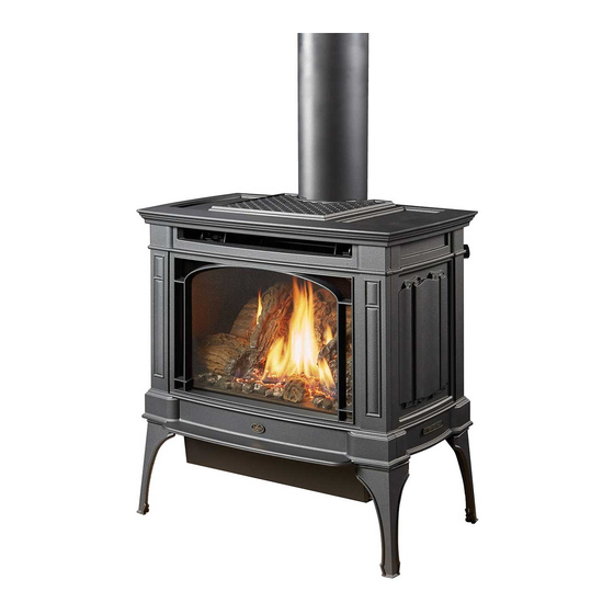
Berkshire MV
Owner's Manual
HOT GLASS WILL CAUSE
BURNS
DO NOT TOUCH GLASS
UNTIL COOLED
NEVER ALLOW CHILDREN
TO TOUCH GLASS
12521 Harbour Reach Dr., Mukilteo, WA 98275
$10.00
Built-in Direct Vent Stove
Natural Gas or Propane
Residential or Mobile Home
French language manuals at travisindustries.com
Manuels de langue Française à travisindustries.com
10/2/17
Tested and Listed by
Report # 0028GF031S
Omni-Test Laboratories, Inc.
Portland, Oregon
ANSI Z21.88-2016
CSA 2.33-2016
CGA 2.17-M91 (R2014)
www.travisproducts.com
100-01454
Advertisement
Table of Contents

Related Manuals for Lopi Berkshire MV


Summary of Contents for Lopi Berkshire MV
- Page 1 Berkshire MV Owner’s Manual WARNING: FIRE OR EXPLOSION HAZARD Failure to follow safety warnings exactly could result in serious injury, death, or property damage. - Do not store or use gasoline or other flammable vapors and liquids in the vicinity of this or any other appliance.
-
Page 2: Important Information
Or, mail your warranty card to: service of any type. Travis Industries House of Fire 12521 Harbour Reach Dr. Model: Berkshire MV Mukilteo, WA 98275 Serial Number: Save Your Bill of Sale. To receive full warranty coverage, you will Purchase Date: need to show evidence of the date you purchased your heater. - Page 3 LP (Propane) Conversion Instructions ..40 Horizontal Termination with One 90° Elbow 15 Optional Blower ..........43 Horizontal Termination with Two Elbows (one 90° vertical and one 90° or 45° horizontal elbow) ..........16 10/2/17 - 1454 Berkshire MV © Travis Industries...
- Page 4 Do not operate if any portion of the heater was submerged in water or if any corrosion occurs. Immediately call a qualified service technician to inspect the appliance and to replace any part of the control system and any gas control which has been under water. © Travis Industries 10/2/17 - 1454 Berkshire MV...
- Page 5 Travis Gas Fireplaces, Stoves, and Inserts are protected by one or more of the following patents; U.S. 8,469,021, 7,066,170, 6,602,068, 6,443,726, 6,953,037; Canada 2755517 as well as other U.S. and Foreign Patents pending. 10/2/17 - 1454 Berkshire MV © Travis Industries...
-
Page 6: Installation Options
Electrical Rating ............. 115 Volts, 1.5 Amps, 60 Hz (180 watt) Fuel This heater is shipped in natural gas (NG) configuration but may be converted to use propane (LP) using a conversion kit (orifices are included, LP regulator is purchased separately). © Travis Industries 10/2/17 - 1454 Berkshire MV... -
Page 7: Installation Warnings
Propane (LP) Orifices and Regulator • Gas Line Equipment (shutoff valve, pipe, etc.) Log Set Touch-Up Paint Installation Overview "Clearances" See "Vent Requirements" See "Gas Line Installation" See "Floor Protection Requirements" 10/2/17 - 1454 Berkshire MV © Travis Industries... -
Page 8: Installation Hints
When the stove is installed in a mobile home, it must be bolted to the floor and the appliance grounded (use the optional blower with a grounded circuit or other suitable grounding method - current ANSI/NFPA 70 or CSA C22.1). © Travis Industries 10/2/17 - 1454 Berkshire MV... -
Page 9: Heater Placement Requirements
Electrical Requirements • Plug the stove into a grounded receptacle supplying a minimum 1.5 amps (115 Volts, 60 Hz, 180 watts). 10/2/17 - 1454 Berkshire MV © Travis Industries... -
Page 10: Optional Wall Switch Or Thermostat Installation
To wire the heater in parallel, follow the directions below: To wire the heater in series, follow the directions below: On / Off Switch On / Off Switch Thermostat (or External Switch) Wires Thermostat (or External Switch) Wires © Travis Industries 10/2/17 - 1454 Berkshire MV... -
Page 11: Gas Line Installation
The supply regulator (the regulator that attaches directly to the residence inlet or to the propane tank) should supply gas at the suggested input pressure listed above. Contact the local gas supplier if the regulator is at an improper pressure. 10/2/17 - 1454 Berkshire MV © Travis Industries... -
Page 12: Vent Requirements
• Horizontal sections require a 1/4" rise every 12" of travel (7mm) (305mm) • Horizontal sections require non-combustible support every three feet (e.g.: plumbing tape) © Travis Industries 10/2/17 - 1454 Berkshire MV... -
Page 13: Approved Vent Configurations
When a horizontal elbow (90° or 45°) is to the top of the termination Elbow used, horizontal length is the sum of the on vertical terminations. two lengths (H1 + H2). Vent Vertical Elbow Height 10/2/17 - 1454 Berkshire MV © Travis Industries... - Page 14 Restrictor Position # 5 20 feet (6m) 20 feet (6m) 15 feet (4.5m) 15 feet (4.5m) 10 feet (3m) 10 feet (3m) 5 feet (1.5m) 5 feet (1.5m) 0 feet 0 feet © Travis Industries 10/2/17 - 1454 Berkshire MV...
- Page 15 Horizontal sections require a 1/4" (0.250mm) rise every 12" (305mm) of travel. 5 feet (1.5m) 5 feet (1.5m) NATURAL GAS: Min. 2' (0.61m) Section Required PROPANE (LP): Min. 3' (0.915m) Section Required 0 feet 0 feet 10/2/17 - 1454 Berkshire MV © Travis Industries...
-
Page 16: Horizontal Termination With Two Elbows
Horizontal sections require a 1/4" (0.250mm) rise every 12" (305mm) of travel. 5 feet (1.5m) 5 feet (1.5m) NATURAL GAS: Min. 2' (0.61m) Section Required PROPANE (LP): Min. 3' (0.915m) Section Required 0 feet 0 feet © Travis Industries 10/2/17 - 1454 Berkshire MV... - Page 17 5 feet (1.5m) 5 feet (1.5m) rise every 12" (305mm) of travel. 0 feet 0 feet These are vertical elbows. This is a horizontal elbow - NOT ALLOWED FOR THIS VENT CONFIGURATION 10/2/17 - 1454 Berkshire MV © Travis Industries...
- Page 18 5 feet (1.5m) 5 feet (1.5m) rise every 12" (305mm) of travel. 0 feet 0 feet These are vertical elbows. This is a horizontal elbow - NOT ALLOWED FOR THIS VENT CONFIGURATION © Travis Industries 10/2/17 - 1454 Berkshire MV...
- Page 19 15 feet (4.5m) 10 feet (3m) 10 feet (3m) NOTE: Horizontal sections require a 1/4" (0.250mm) 5 feet (1.5m) 5 feet (1.5m) rise every 12" (305mm) of travel. 0 feet 0 feet 10/2/17 - 1454 Berkshire MV © Travis Industries...
- Page 20 NOTE: Measure clearances to the nearest edge of the exhaust hood. • Use the vinyl siding standoff when installing on an exterior with vinyl siding. • Vent termination must not be located where it will become plugged by snow or other material © Travis Industries 10/2/17 - 1454 Berkshire MV...
-
Page 21: Class A Chimney Conversion Kit
Retro Connector Simpson Duravent Direct Connector to the Vent Pipe Sections Retro Vertical Top Flex Pipe (use adjustable section) Additional Required Equipment: 4" Flex (#711 or U.L. 1777) Termination (#991) Co-Axial Sections 10/2/17 - 1454 Berkshire MV © Travis Industries... -
Page 22: Interior Masonry Chimney Conversions
Minimum vertical rise is 10' (3M) • See the chart on page 18 for determining the correct restrictor position. NOTE: these restrictor positions are based upon lab tests. The ideal restrictor position may vary slightly. © Travis Industries 10/2/17 - 1454 Berkshire MV... -
Page 23: Log Installation
The log stands are shipped on top of the burner. Make sure they are in place with the mounting studs inserted through the holes on the stands. The rear log has two holes on the bottom. Place it over the two tabs at the back of the firebox. 10/2/17 - 1454 Berkshire MV © Travis Industries... - Page 24 The left log has two holes on the bottom. Place the log so the holes fit over the two mounting studs on the left log stand. The right log has two holes on the bottom. Place the log so the holes fit over the two mounting studs on the right log stand. © Travis Industries 10/2/17 - 1454 Berkshire MV...
- Page 25 The right cross log has one hole on the bottom. Place the log so the hole fits over the right pin on the rear log. The front of the log rests on the right log (see picture for orientation). 10/2/17 - 1454 Berkshire MV © Travis Industries...
-
Page 26: Ember Placement
Place a layer of embers along the edges of the burner, on top of rivets, and along the edges to enhance the aesthetics of the firebox. Do not place embers over any burner holes. See the photo to the right. © Travis Industries 10/2/17 - 1454 Berkshire MV... -
Page 27: Steps For Finalizing The Installation
Standard Screwdriver Thermopile Pilot Hood 3/8” Thermocouple 7. Replace the glass. 8. Start the main burner and verify the burner ignites correctly. 9. Leak test all gas joints. 10/2/17 - 1454 Berkshire MV © Travis Industries... -
Page 28: Air Shutter Adjustment
The flames should burn off of each burner hole. If the heater does not work correctly, contact your Travis dealer for a remedy. 12. Give this manual to the home owner for future reference and fully explain operation of this heater. © Travis Industries 10/2/17 - 1454 Berkshire MV... -
Page 29: Face And Glass Removal
Swing the glass frame into place - you may have to lift it slightly to allow it to fit over the top of the firebox. c) Attach the upper latches (follow the instructions above in reverse). d) Replace the stove front and top. 10/2/17 - 1454 Berkshire MV © Travis Industries... - Page 30 Top of Firebox Glass Frame Anchor Note how the washer on the latch fits behind the flange on the glass frame anchor. Once fully inserted, turn the latch until it is upright. © Travis Industries 10/2/17 - 1454 Berkshire MV...
-
Page 31: Before You Begin
This button is used only to start the pilot. When pressed it sends an electrical charge to the pilot assembly. This creates a blue spark directly next to the pilot, igniting the pilot flame. On/Off Switch This switch turns the main burner on and off. 10/2/17 - 1454 Berkshire MV © Travis Industries... -
Page 32: Starting The Pilot
“f”. Replace the glass. Turn the gas control knob counter-clockwise to "ON". The pilot is now lit and the heater can be turned on and off. © Travis Industries 10/2/17 - 1454 Berkshire MV... -
Page 33: Starting The Heater For The First Time
Your heater has an adjustable flame to tailor the look and heat output to your specific needs. It is adjusted by turning the middle dial on the gas control valve. Index Mark Flame Height Adjustment Knob Turn counter-clockwise to adjust the flame higher, clockwise to lower. 10/2/17 - 1454 Berkshire MV © Travis Industries... -
Page 34: Normal Operating Sounds
This is normal during start-up. You may notice the smell is more acute if the appliance was left idle for a long period. Power Outages The heater will work if household current (AC power) is disconnected. © Travis Industries 10/2/17 - 1454 Berkshire MV... -
Page 35: Painted Surfaces
Remove any debris or vegetation near the vent termination. Contact your dealer if any sooting or deterioration is found near the vent termination. Venting system should be examined by a qualified agency. 10/2/17 - 1454 Berkshire MV © Travis Industries... -
Page 36: Troubleshooting Table
Short (Under 6") The logs or coals are placed incorrectly See "Log Set Installation" Thin Layer of Soot Improper air shutter adjustment Adjust Air Shutter - contact your dealer Covers the Glass © Travis Industries 10/2/17 - 1454 Berkshire MV... -
Page 37: Replacement Parts List
Thermocouple Thermopile Piezo Igniter On/Off Switch (on fireplace) Brown Copper Co-Axial Wire Orange Spark Electrode White Pilot Hood Optional Wall Switch, Thermostat, or Remote Control Optional Blower Wiring 10/2/17 - 1454 Berkshire MV © Travis Industries... - Page 38 Safety Label Safety Label The safety (listing) label is attached to the operating tag (chained to the heater near the gas control valve). A copy is shown below © Travis Industries 10/2/17 - 1454 Berkshire MV...
-
Page 39: Burner Assembly
4. Check with your dealer in advance for any costs to you when arranging a warranty call. Mileage or service charges are not covered by this warranty. This charge can vary from store to store. 10/2/17 - 1454 Berkshire MV © Travis Industries... - Page 40 Convert the appliance prior to installing the gas line to ensure proper gas use. 1. Remove the glass frame. Remove the logs (if installed). 2. Remove the two log stands. 3. Remove the 2 screws holding the burner in place. 1/4" Nutdriver © Travis Industries 10/2/17 - 1454 Berkshire MV...
- Page 41 15/16" Screw the LP orifice until orifice 23.8mm protrudes 15/16" (23.8mm) indicating full insertion (use Look here for the orifice identification wrench to secure manifold when re-attaching orifice). 10/2/17 - 1454 Berkshire MV © Travis Industries...
- Page 42 (remove glass, bleed gas line, leak test gas connections, start the heater, inspect pilot flame, adjust air-shutter, and inspect burner performance). Verify gas output pressure (manifold pressure) at this time (see the section “Gas Line Requirements” for details). © Travis Industries 10/2/17 - 1454 Berkshire MV...
-
Page 43: Optional Blower
Optional Blower Installation WARNING: Do not plug the blower in until it is fully installed and grounded. Do not connect 110-120 VAC to the gas control valve or wiring system of this appliance. 10/2/17 - 1454 Berkshire MV © Travis Industries... - Page 44 Installation Overview .......... 7 45° Elbows ........... 14 Installation Warnings .......... 7 Wiring Diagram ..........38 Interior Masonry Chimney Conversions ... 22 Yearly Service Procedure ........ 35 Location of Controls ......... 31 © Travis Industries 10/2/17 - 1454 Berkshire MV...
Need help?
Do you have a question about the Berkshire MV and is the answer not in the manual?
Questions and answers