
Related Manuals for Sola Hevi Duty S4K4U6000


Summary of Contents for Sola Hevi Duty S4K4U6000
- Page 1 OWER VAILABILITY S4K4U6000 U ANUAL 120/208V On-Line UPS 120/208V 120/240V...
-
Page 3: Table Of Contents
TABLE OF CONTENTS ..........1 MPORTANT AFETY NSTRUCTIONS... - Page 4 S4K4U6000 Configuration Program Features ........
- Page 5 10.0 ........... 30 ODES OF PERATION 10.1...
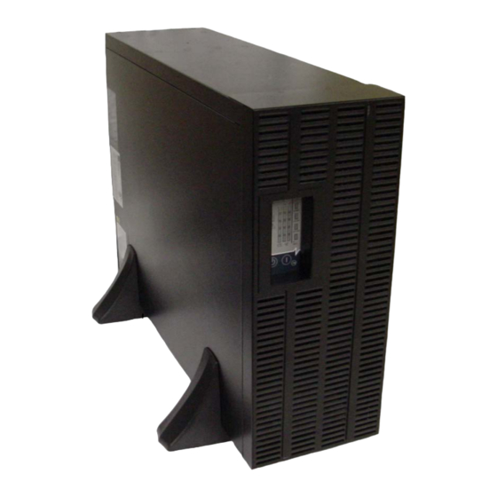
- Page 6 FIGURES Figure 1 6 kVA Dual Inverter S4K (front and rear views) ........7 Figure 2 Support base and spacers .
-
Page 7: Important Safety Instructions
Do not continue to use the UPS if the front panel indications are not in accordance with these operating instructions or if the UPS performance alters in use. Refer all faults to your local dealer, Sola/Hevi-Duty representative or Sola/Hevi-Duty Technical Services. - Page 8 When replacing batteries, replace with the same Sola/Hevi-Duty authorized replacement battery kits. CAUTION Do not dispose of battery or batteries in a fire. The battery may explode. Do not open or mutilate the battery or batteries. Released electrolyte is harmful to skin and eyes. It may be toxic.
-
Page 9: Glossary Of Symbols
Glossary of Symbols LOSSARY OF YMBOLS Risk of electrical shock Indicates caution followed by important instructions AC input AC output Requests the user to consult the manual Indicates the unit contains a valve-regulated lead acid battery PbH2SO4 Recycle DC voltage Equipment grounding conductor Bonded to ground AC voltage... -
Page 10: Introduction And System Description
It supplies connected equipment with clean sinewave power. Sensitive electronic equipment operates best from sinewave power. For ease of use, the S4K4U6000 features a light-emitting diode (LED) display to indicate both load percentage and battery capacity. It also provides self-diagnostic tests, a combination ON/Alarm Silence/Battery Test button, a Standby button, user configurable program and two levels of alarms when the unit is operating on battery. -
Page 11: System Description
Battery Charger The battery charger utilizes energy from the utility power and precisely regulates it to continuously float charge the batteries. The batteries are being charged whenever the S4K4U6000 is plugged in, even when the UPS is not turned on. -
Page 12: Dc To Dc Converter
Optional external battery cabinets are available to extend battery run times. Dynamic Bypass The S4K4U6000 provides an alternate path for utility power to the connected load in the unlikely event of a UPS malfunction. Should the UPS have an overload, overtemperature or UPS failure condi- tion, the UPS automatically transfers the connected load to bypass. -
Page 13: Major Components
Major Components AJOR OMPONENTS The S4K4U6000 is composed of three major assemblies to provide easier handling, installation and versatility. Main Frame and Electronics This 4U cabinet arrives without internal batteries to lighten the UPS for easier installation. Once the cabinet has been placed in its final floor or rack position, the internal batteries may be installed. The UPS is shipped with a hardwire distribution box with manual bypass switch. -
Page 14: Removable Power Distribution Box
Major Components Removable Power Distribution Box The UPS is shipped with a bypass hardwire power distribution pack installed. For maximum flexibil- ity, this may be easily replaced with either of two optional power distribution boxes that provide the benefits of hardwire input and output plus manual bypass switch or plug/receptacle convenience with manual bypass switch. -
Page 15: What ' S Included
What’s Included ’ NCLUDED The S4K4U6000 is shipped with the following items: • S4K4U6000 user manual • Vertical display overlay • Front bezel • Battery cover grille • MultiLink software CD • MultiLink serial cable, 10 ft (3m) • Rack mount handles •... -
Page 16: Installation And Configuration
UPS operation in sustained temperatures above 77°F (25°C) reduces battery life. Install the Main Cabinet The S4K4U6000 may be installed either as a tower unit or in a rack, depending on available space and use considerations. Determine the type of installation and follow the appropriate instructions in either 6.1.1 - Tower UPS Installation or 6.1.2 - Installing the Adjustable Rack-Mount Kit—... -
Page 17: Installing The Adjustable Rack-Mount Kit-Sold Separately
Installation and Configuration 6.1.2 Installing the Adjustable Rack-Mount Kit—Sold Separately This kit contains parts needed to mount several different models of UPS and external battery cabi- nets into EIA310-D standard four-post racks that are 18-32" deep (457-813mm). The weight limit per pair of adjustable rack-mounting brackets is 200 pounds (91 kg). - Page 18 Installation and Configuration 4. Get eight (8) M4 screws and eight (8) M4 nuts from the M4 nuts hardware pack in this kit. Each nut has a locking, nylon screws insert that begins gripping the screw when it is halfway tight.
-
Page 19: External Battery Cabinet Installation
Installation and Configuration External Battery Cabinet Installation Optional Sola/Hevi-Duty external battery cabinets may be connected to the UPS to provide additional battery run time. External battery cabinets are designed to be placed on one side of the UPS or stacked beneath the UPS. -
Page 20: Connect Input/Output Power
Installation and Configuration Connect Input/Output Power The UPS ships with the basic hardwire box attached. If an optional model is to be used, remove the standard box and install the optional box using the three captive mounting Slide screws marked in the illustration, below, right. cover over 6.3.1... -
Page 21: S4Kpad-Hdwr And S4Kpad-Hdwr-Mbs Terminal Block Connections
Installation and Configuration 6.3.3 S4KPAD-HDWR and S4KPAD-HDWR-MBS Terminal Block Connections Conduit entry holes are provided on the rear and side of the box. Input and output wiring should not share the same conduit. Table 1 Electrical requirements—S4KPAD-HDWR and S4KPAD-HDWR-MBS Input Current Recommended (Max.) Recommended Wire Maximum Wire... -
Page 22: Install The Grounding Electrode Conductor
A grounding electrode conductor (GEC) must be installed in accordance with national and local wiring codes and regulations. Install the Internal Battery Pack To facilitate shipping and installation, the S4K4U6000 ships with- out the internal battery installed. Once the UPS is installed in place, Controls the internal battery pack must be installed. -
Page 23: Initial Startup And Electrical Checks
Initial Startup and Electrical Checks NITIAL TARTUP AND LECTRICAL HECKS Initial Startup and the Configuration Program—The UPS ships with a default 120 VAC L-N setting. This is also the most robust setting in that it can operate with either input phase angle (120 or 180 degrees). -
Page 24: L14-30P Plug-In Connections-Including The S4Kpad-001 Distribution Box
Initial Startup and Electrical Checks L14-30P Plug-in Connections—Including the S4KPAD-001 Distribution Box WARNING Miswiring power to the input (L1-L2-N-G) or connecting to single phase voltages (L-N-G only) may damage the UPS. A qualified electrician should verify that the L14-30R is properly wired before attaching the UPS. -
Page 25: Configuration Program
8.1.1 What You Will Need In addition to the S4K4U6000 UPS, you will need the configuration program diskette and serial cable (beige or tan, three-wire: GND, TX, RX; straight through 2-2, 3-3, 5-5) included in the UPS accessory ®... -
Page 26: Configuration Program-Installation
2. When you see this PreSetup window, select OK. This will open the main installation screen. 3. Click NEXT to continue installing the configuration program. Sola/Hevi-Duty recommends using the default installation options, but you will be given the option to make modifications to the standard entries. -
Page 27: Establishing Communication Link With The Ups
Configuration Program Establishing Communication Link with the UPS Use only the serial communication cable supplied with the configuration program. If an accessory communication card has been installed in the UPS’s communication card slot, the option card must be removed while using the configuration program. Use the serial communication cable to connect your computer’s COM1 port to the DB-9 communica- tion port on the rear of the UPS. -
Page 28: Configuration Program-Operation
Configuration Program Configuration Program—Operation 8.4.1 Read/Confirm UPS Configuration Settings The UPS settings may be monitored, but not changed, using the configuration program while the UPS is operating in any mode. If the program is only used to read the present UPS settings, close the pro- gram using the CANCEL button. -
Page 29: Ups Tab
Configuration Program UPS Tab When the program starts, the following window will open displaying the UPS model along with the current UPS settings. This information can be updated at any time using the REFRESH button. Figure 4 Factory default settings for 120VAC UPS 8.5.1 Output Voltage The Output Voltage displayed is the nominal input/output voltage. -
Page 30: Frequency Selection
Configuration Program 8.5.4 Frequency Selection The UPS is normally designed for 50Hz or 60Hz operation. The factory default corresponds to the model. All models are capable of being used as 50Hz or 60Hz systems. The UPS will automatically sense the utility frequency when first plugged in and set the nominal frequency to match. Therefore, for all normal use the Auto Sense button should be selected. -
Page 31: Options Tab Used With Earlier S4K Models
Configuration Program Options Tab Used With Earlier S4K4U Models This version of the configuration program will accompany S4K4U UPS models that support new pro- gramming features accessible using the Options tab. If version 1.6 (or later) is used with an earlier S4K4U model (with an earlier UPS firmware version), the Any Mode Shutdown features cannot be changed. -
Page 32: Battery Tab
Configuration Program Battery Tab Factory default settings illustrated. The boxes on the right show the available options using the drop-down selection boxes. 8.8.1 Low Battery Time Warning The UPS will estimate remaining operating time when on batteries. A low battery alarm is activated if the estimated time reaches the Low Battery Time. -
Page 33: About Tab
Configuration Program About Tab The version number of the configuration program may be confirmed using the About Tab. -
Page 34: Controls And Indicators
ON - Pressing this button will start up the UPS in order to provide conditioned and protected power. Alarm Silence - To silence alarms, press this button for at least one Second. After the alarm is silenced, the S4K4U6000 will reactivate the alarm system to alert of addi- tional problems. NOTE The LOW BATTERY and BYPASS reminder alarms CANNOT be silenced. -
Page 35: L1 & L2 Load Level Indicators (Two Rows Of Indicators: 4 Green, 1 Amber)
The Battery Level indicators display approximate battery capacity at all times. Each indicator repre- sents an approximate 20 percent increase in battery capacity. The S4K4U6000 is equipped with automatic and remote battery test features. The automatic test occurs every 14 days (this option is user-configurable) if utility has not been interrupted. Should the battery fail this test, the red Fault indicator along with the A and C diagnostic indicators will illumi- nate and an alarm will sound (refer to 13.0 - Troubleshooting). -
Page 36: Modes Of Operation
Modes of Operation 10.0 M ODES OF PERATION 10.1 Normal Mode Operation During normal operation, utility power provides energy to the UPS. The filters, power factor correction circuit and the inverter process this power to provide computer grade power to connected loads. The UPS maintains the batteries in a fully charged state. -
Page 37: Communications
OMMUNICATIONS 11.1 Communications Interface Port The S4K4U6000 UPS has a standard DB-9 serial port female connector located on the rear of the UPS unit. Several signals are provided on this port and are assigned as follows: Table 3 DB-9 pin assignment... -
Page 38: Pin 4 - Remote Shutdown On Battery
License Kits, visit our Web site (www.solaheviduty.com) or contact your local dealer, Sola/Hevi- Duty representative or Sola/Hevi-Duty Technical Services. Several option cards are available for use in the Intellislot port of the S4K4U6000 The Intellislot SNMP WEB CARD provides SNMP and Web-based monitoring and control of the UPS across the net- work. -
Page 39: Remote Emergency Power Off
Communications 11.4 Remote Emergency Power Off The UPS is equipped with a Remote Emergency Power Off (REPO) connector. The user must supply a means of interfacing with the REPO circuit to allow disconnecting the UPS input feeder breaker to remove all sources of power to the UPS and connected equipment to comply with national and local wiring codes and regulations. -
Page 40: Maintenance
Failure to recharge the batteries peri- odically will permanently degrade battery capacity. The S4K4U6000 is designed to allow the user to safely replace the internal batteries. Read the safety cautions before proceeding. Contact your local dealer or Sola/Hevi-Duty representative to obtain the appropriate replacement battery kit part number and pricing. -
Page 41: Ups Replacement
Maintenance 12.2 UPS Replacement When using a power distribution box with bypass, the UPS can be removed while powering the load through the Bypass Switch. NOTE During the procedure, the connected load will not be protected from power disturbances, such as spikes, sags and failure. -
Page 42: Troubleshooting
5 minutes while the battery charger is not operational. If a problem persists, consult your local dealer or Sola/Hevi-Duty representative. Please have the UPS model number and serial number available at the time of your inquiry. -
Page 43: Table 5 Alarm Conditions
Check load level display and reduce the load on the UPS. time. Replace batteries. Contact your local dealer, Sola/Hevi- Batteries may not be able to Duty representative or Sola/Hevi-Duty Technical Support hold a full charge due to age. Services for replacement battery kit. Fault and Bypass indicators Check load level display and remove non-essential loads. - Page 44 Fault indicator and diagnostic Replace batteries. Contact your local dealer, Sola/Hevi- indicators A and C are UPS failed the battery test. Duty representative or Sola/Hevi-Duty Technical Support illuminated. Services. Only phase angles of 120, 180 or 240 degrees (±10 degrees) are permitted. These must be compatible with the selections in the configuration program.
-
Page 45: Table 7 Battery Run Times
Troubleshooting Using the configuration program, the user may specify the number of S4K4U6000 external battery cabinets attached to the UPS. The factory default is programmed for internal batteries only. Table 7 shows estimated run times at different loads. Table 7... -
Page 46: Auto-Learning Battery Run Times
13.1 Auto-Learning Battery Run Times As batteries age, the estimated run times may become less accurate. The S4K4U6000 is programmed to “learn” from a full battery discharge and modify the estimated run time for the measured battery capacity. This can improve accuracy and compensate for aging batteries or batteries that operate at different ambient temperatures. -
Page 47: Specifications
Specifications 14.0 S PECIFICATIONS Table 8 UPS specifications Model Number S4K4U6000 4200W/5200VA at 127/220 (120 or 240 degrees only) 4200W/5200VA at 120/208 (120 or 240 degrees) 4200W/6000VA at 120/240 (180 degrees) Model Rating 4200W/6000VA at 115/230 (180 degrees only) 3780W/5400VA at 110/220 (180 degrees only) -
Page 48: Table 9 Battery Specifications
Specifications Table 8 UPS specifications (continued) Model Number S4K4U6000 ENVIRONMENTAL Operating Temp +32°F to +104°F (0°C to +40°C) Storage Temp +5°F to +122°F (-15°C to +50°C) Relative Humidity 0% to 95%, non-condensing Operating Elevation Up to 10,000 ft. (3000m) at 104°F (40°C) without derating Storage Elevation 50,000 ft. -
Page 49: Product Warranty Registration
Table 11 External battery cabinet specifications Model Number S4K144BAT Used w/ UPS Model S4K4U6000 DIMENSIONS in (mm) Unit (with bezel) W x D x H 3.5 x 24.2 x 17 (87 x 618 x 430) Shipping W x D x H 10.5 x 27.2 x 23 (268 x 692 x 585) - Page 50 Specifications...
- Page 52 © 2005 Sola/Hevi-Duty. All rights reserved throughout the world. Specifications subject to change without notice. ® Sola/Hevi-Duty name and logo are registered trademarks of EGS Electrical Group, LLC. Intellislot is a registered trademark of Emerson Network Power. Multilink is a trademark of Emerson Network Power. All names referred to are trademarks or registered trademarks of their respective owners.
Need help?
Do you have a question about the S4K4U6000 and is the answer not in the manual?
Questions and answers