Table of Contents
Advertisement
Quick Links
Advertisement
Table of Contents

Related Manuals for Sunrise Medical Little Star


Summary of Contents for Sunrise Medical Little Star
- Page 1 Service and Maintenance for Scooters Workshop Manual Little Star (4 Wheel)
-
Page 2: Table Of Contents
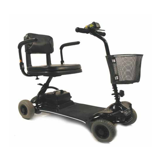
Table of Contents The Little Star mobility scooter is a versatile indoor/occasional outdoor, 4-wheeled machine. Features include; Folding tiller assembly, moulded lightweight padded seat with width adjustable armrests, 2” seat height adjustment, 2-Amp off-board automatic charger, This product is manufactured to comply with the requirements of... -
Page 3: Product Information
Product Information It is potentially hazardous to fit or use any parts other than genuine Sunrise Medical parts. The company disclaims all liability for the consequences of such use, which in addition, voids the machine warranty. This vehicle is for the carriage of ONE PERSON And MUST NOT be used for any other purpose. -
Page 4: Safety Information
Safety Information Whilst working on powered mobility products, it is essential to observe good working practice. Below are a series of safety guidelines and recommendations. Please note that these precautions are intended to serve only as a guide and are not intended to supersede or replace any safety statute, NHS or other safety regulations. - Page 5 Safety Information Batteries • When the tops of batteries are exposed, take extra care when working on or around the terminals. • Do not allow metal tools to drop on to or touch the exposed terminals of the batteries or other exposed connections as this could cause a short circuit, which may result in an explosion.
-
Page 6: Recommended Tools
Tools Required Recommended Tools • The following list of tools should enable any task to be dealt with. Some will only occasionally be needed, but it is advisable to own or have access to them. 1. Metric socket set 2. Imperial socket set 3. -
Page 7: Service/Inspection
Service & Inspection (Annual) Controller Chassis • On/off Switch • Condition, (Welded Joints etc.) • PCB Plug Connections • Steering, (Twists etc.) • Operation • Dynamic Braking Upholstery / Seat • Programmable Settings, (where applicable) • Seat • Test Run •... -
Page 8: Technical Specifications
Technical Specifications Little Star Overall length 38” / 96cm Overall width 20” / 50cm Maximum user weight 250lbs / 18st / 113kg Maximum gradient 6 degrees Range 8m / 12km Speed 4mph / 6kph Turning radius 43” / 110cm Weight 77lbs / 35kg including batteries. -
Page 9: Front Wheels (4-Wheel)
C HAPT E R O N E FRONT WHEELS Front Wheels 1. Use a thin-blade knife to..2. carefully prize off the hubcap. 3. Use a cross-head screwdriver to undo 4. Pull the Front Wheel from the Stub Axle. the centre wheel securing bolt. 5. -
Page 10: Rear Wheels
C HA P T E R T WO REAR WHEELS Rear Wheels 1. Use a thin-blade knife to lift the hub cap. 2. Undo the centre bolt using a 13.00mm socket. 3. Remove the centre bolt, noting the posi- 4. Carefully remove the wheel, taking care not to lose the Drive Key. -
Page 11: Seat & Armrests
C H A P T ER THRE E SEAT & ARMRESTS Seat & Armrests 1. Shows the seat in operating position. 2. Fold the Backrest down. 3. Loosen the seat locking lever by turning 4. Lift the Seat assembly off. anti-clockwise. - Page 12 C H A P T ER THRE E SEAT & ARMRESTS 7. Undo the hand-wheel by tuning it anti- 8. Remove the Armrests or adjust them to clockwise. the desired width. 9. Hold the top of the Seat Stem & grab 10.
-
Page 13: Battery Box
C H A P T ER FO UR BATTERY BOX Battery Box 2. Shows the power lead connected to the 1. The Battery Box in situ. battery. 3. remove the power lead by pressing in the 4. Use the handle to lift the Battery Box metal tab on the battery socket. -
Page 14: Batteries & Battery Box
C H A P T ER FIV E BATTERIES & BATTERY BOX Batteries & Battery Box 1. Shows the location of the 12 battery box 2. Undo the screws using a long phillips screws beneath the lip of the battery box. screwdriver. - Page 15 CHA P T ER F IVE BATTERIES & BATTERY BOX 7. Lift each battery clear of the battery box. 8. Shows the battery box base. 10. View of the battery main lead and up the lid on the fuse holder and pull the socket.
- Page 16 C HA P T ER F IVE BATTERIES & BATTERY BOX 13. Remove the charging socket. the cable connecting the charge socket to the fuse holder. 15. Once removed carefully lift the tab on 16. Using a 14mm ring spanner undo the the connectors ready for re-assembly.
-
Page 17: Rear Drive Assembly Panels
C H A P T ER S IX REAR DRIVE ASSEMBLY PANEL Rear Drive Assembly Panel 1. With the seat removed, use a phillips 2. Slide out the rear panel by angling it screwdriver to undo the rear panel retaining slightly through the rear frame. -
Page 18: Rear Drive Assembly Motor Leads
C H A P T ER S EV E N REAR DRIVE ASSEMBLY MOTOR LEADS Rear Drive Assembly Motor Leads 1. Using long-nosed pliers bend open the 2. Disconnect the power plug & socket. clip around the power terminal plug. -
Page 19: Rear Drive Assembly Motor/Brake
C H A P T ER E IG HT REAR DRIVE ASSEMBLY MOTOR/BRAKE Rear Drive Assembly Motor/Brake 1. To inspect the micro-switch, lift the plastic 2. The micro-switch can then be accessed. end cover off the motor. 4. and a 5.00mm hex key is required. 3. - Page 20 C H A P T ER E IG HT REAR DRIVE ASSEMBLY MOTOR/BRAKE 7. Gently ease the motor away from the 8. Lift the motor clear of the chassis. transaxle. Coupling 10. Shows the position of the freewheel the motor must line up with the drive shaft extension lever held by 2 phillips screws.
-
Page 21: Rear Drive Assembly Transaxle
C H A P T ER NI NE REAR DRIVE ASSEMBLY TRANSAXLE Rear Drive Assembly Transaxle Coupling 1. The drive coupling on the transaxle 2. Location of 2 of the transaxle mounting gearbox, must aline with the motor drive bolts. coupling when reassembled. - Page 22 C H A P TE R NINE REAR DRIVE ASSEMBLY TRANSAXLE 8. The transaxle assembly without motor/ 7. Carefully remove the rubber mounts for brake. inspection.
-
Page 23: Tiller Assembly
C H A P T ER TE N TILLER ASSEMBLY Tiller Assembly 1. View of the tiller locking mechanism. 2. The two lower tiller mounting studs. 3. Lower the tiller by turning the black screw 4. Shows the tiller locking screw and lock- anti-clockwise. - Page 24 C H A P T ER TE N TILLER ASSEMBLY 7. Move the panel over to expose the con- 8. Shows the controller and main wiring troller and main wiring looms. looms. 10. Do this all the way along to the control- 9.
- Page 25 C H A P T ER TE N TILLER ASSEMBLY 13. Release the tiller loom from the control 14. Carefully feed the tiller cable through box connector. the front panel and lift the tiller clear. 15. Undo the upper tiller mounting studs 16.
-
Page 26: Main Controller
C H A P T ER E LE V E N MAIN CONTROLLER Main Controller 1. Unplug the tiller loom from the main 2. Using long-nosed pliers and wire cutters controller. release the motor and power cable from their ties. 3. -
Page 27: Front Panel
C HA P TE R TWELVE FRONT PANEL Front Panel 1. With the battery and tiller removed lift up 2. Move the panel away from the velcro and the front panel from the rear pulling it off the put in a position ready to lift clear. frame clips and velcro. -
Page 28: Steering Head
C H A P T ER THIRT EEN STEERING HEAD Steering Head 2. Remove the steering head nut using your 1. Use a large adjustable spanner to loosen the steering head nut. 3. Undo the bearing retaining nut. 4. Using long-nosed pliers carefully remove the steering head upper bearing. - Page 29 C H A P T ER THIRT EEN STEERING HEAD 8. Remove the spacer and bolt from the 7. Remove the steering link from the steer- steering head bracket. ing head bracket. 9. Lower the steering head bracket out of 10.
-
Page 30: Main Frame Steering
C H A P T ER FO URTEE N MAIN FRAME STEERING Main Frame Steering 1. Use a 13mm socket and spanner to re- 2 Remove the self locking nut from the top. move the other end of the steering link. 3. - Page 31 C H A P T ER FO URTEE N MAIN FRAME STEERING 7. Use a 13.00mm socket & spanner to 8. Remove the self-locking nut from the top. undo the other end of the steering link. 9. Lower the bolt out of the stub axle and 10.
-
Page 32: Main Frame Stub Axle
C H A P T ER FIF TE E N MAIN FRAME STUB AXLES Main Frame Stub Axles 1. The Stub Axle is secured by a 19.00mm 2. Remove the nut and the spacer. nut. 4. Remove the Stub Axle assembly Repeat 3. -
Page 33: Front Frame Bump Stops
C H A P T ER S IX TE EN FRONT FRAME BUMP STOPS Front Frame Bump Stops 1. Using an allen key remove the bolt hold- 2. Show view from the underside of cross ing the front axle cross member. member. -
Page 34: Tiller Assembly
C H A P T ER S EV E NT EE N TILLER ASSEMBLY Tiller Assembly 1. Remove the Tiller assembly as previously 2. The Loom Clips can be removed with a described. 3. Undo the four screws in the bottom of the 4. - Page 35 C H A P T ER S EV E NT EE N TILLER ASSEMBLY 7. Using a small phillips screwdriver undo 8. Carefully lift open the fascia control box. the 4 screws in the underside corners of the fascia control box. 10.
- Page 36 C H A P T ER S EV E NT EE N TILLER ASSEMBLY 14. Undo the locking nut with a ring span- lift off the speed control knob. ner. 15. Remove the locking nut and washer 16. Shows the speed potentiometer. from the speed potentiometer.
- Page 37 C H A P T ER S EV E NT EE N TILLER ASSEMBLY 19. Using a small phillips screwdriver undo the wig-wag retaining screw. 21. Using a small phillips screwdriver remove the 4 screw holding the wig-wag potentiometer. 23. The wig-wag potentiometer.
- Page 38 E N D Please use this Workshop Manual in conjunction with the Little Star Owners Manual and Parts Manual.
Need help?
Do you have a question about the Little Star and is the answer not in the manual?
Questions and answers