Table of Contents
Advertisement
Advertisement
Table of Contents

Related Manuals for Sunrise Medical EMERALD


Summary of Contents for Sunrise Medical EMERALD
- Page 1 EMERALD 4-WHEEL Scooters Workshop Manual...
-
Page 3: Table Of Contents
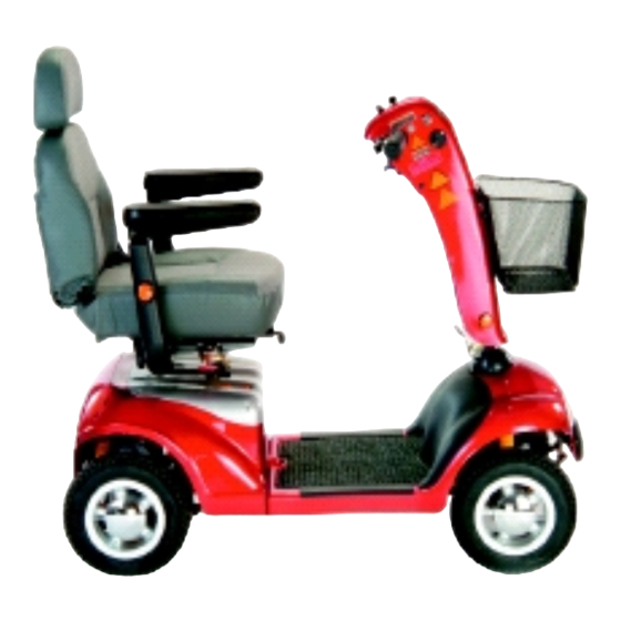
EMERALD WORKSHOP MANUAL The Emerald mobility scooter is a versatile outdoor/indoor, 4-wheeled machine. Features include; Adjustable Tiller assembly, Padded seat with width adjustable armrests, Seat slide, Seat swivel, Headrest, 3-Amp off-board automatic charger, Integrated lights & indicators, Hazard warning lights, Front shopping basket and Carpeted floor matt. - Page 4 IMPORTANT It is potentially hazardous to fit or use any parts other than genuine Sunrise Medical parts. The company disclaims all liability for the consequences of such use, which in addition, voids the machine warranty. This vehicle is for the carriage of ONE PERSON And must not be used for any other purpose.
-
Page 5: Safety Information
EMERALD Safety Whilst working on powered mobility products, it is essential to observe good working practice. Below are a series of safety guidelines and recommendations. Please note that these precautions are intended to serve only as a guide and are not intended to supersede or replace any safety statute, NHS or other safety regulations. - Page 6 EMERALD Safety Batteries • When the tops of batteries are exposed, take extra care when working on or around the terminals. • Do not allow metal tools to drop on to or touch the exposed terminals of the batteries or other exposed connections as this could cause a short circuit, which may result in an explosion.
-
Page 7: Recommended Tools
RECOMMENDED TOOLS 1. Metric socket set. 2. Imperial socket set. 3. Hexagon wrenches, (imperial & metric). 4. 3.5 - 8mm flat screwdriver. 5. No. 0 cross-head screwdriver. 6. No. 1 cross-head screwdriver. 7. No. 2 cross-head screwdriver. 8. Metric combination spanner set 5 - 25mm 9. -
Page 8: Service/Inspection
Service & Inspection ANNUAL Controller Electrical • On/off Switch • Loom • PCB Plug Connections • Connections • Operation • Lights/Indicators • Dynamic Braking • Programmable Settings, (where applicable). • Test Run Drive • Batteries Forwards • Reverse • Physical Inspection •... -
Page 9: Technical Specifications
TECHNICAL SPECIFICATIONS Overall Length 48" / 122 cm Overall Width 22" / 55 cm Maximum user weight 300 lbs / 137 kg / 21 st Maximum Gradient 14 degrees - 115 kg user weight 11 degrees - 137 kg user weight Range 22 m / 36 km Speed 6 mph / 9.5 kph Turning Radius 55"... - Page 10 EMERALD WHEELS FRONT 1. Use a flat-blade screwdriver to 2. carefully prize off the chrome hubcap 3. Use a 13.00mm socket wrench to 4. Note the use of thread-lock on the undo the centre wheel securing bolt. bolt. Be careful not to breath in the powder residue.
-
Page 11: Front Wheels
EMERALD WHEELS FRONT..7. Carefully remove the wheel assem- 8. There are 4 nuts & bolts securing bly. Note that there is no drive shaft the wheel bearing hub. key on the front wheels. 9. Use a 13.00mm socket to loosen 10. - Page 12 EMERALD WHEELS FRONT..13. Remove the bolts & carefully lift 14. The wheel, bearing hub and bolts. out the wheel hub. 16. Location of the five wheel rim studs. 15. View of the enclosed ball-race The numbers indicate the re-tightening bearings.
-
Page 13: Rear Wheels
EMERALD WHEELS REAR 1. Use a flat-blade screwdriver to 2. carefully prize off the chrome hub cap. 4. On the rear wheel hub there is a 3. Note that the centre nut has an extra spacer fitted. key-way cut which corresponds to the key-way on the drive shaft. -
Page 14: Tyres & Tubes
EMERALD WHEEL, TYRE & INNER TUBE 1. Remove the valve dust cap. 2. Use a small screwdriver or similar, to depress the valve pin and let out as much air as possible. 4. Press down on the tyre with the ball 3. - Page 15 EMERALD WHEEL, TYRE & INNER TUBE 7. It is now possible to carefully re- 8. If the inner rim is to be removed, move and replace the inner tube. use a suitable tyre lever as before. 9. Lift the rim away from the tyre.
-
Page 16: Seating
EMERALD SEATING 1. Lift the armrests up for easy ac- 2. Pull the seat recline lever upwards. cess. 3. Allow the backrest to fold flat. 4. Stand behind the seat & lift the seat swivel lever up. 5. With the seat swivel lever in the up 6. - Page 17 EMERALD SEATING..7. To retract the armrest, simply pull it 8. Turn the seat assy. up side down to out. expose the 4-bolts securing the swivel pate. 9. Use a 13.00mm socket wrench to 10. Remove the nuts & washers.
- Page 18 EMERALD SEATING ..13. Lift off the armrest adjuster 14. With the seat slides set fully for- ward, the two rear studs can be bracket. accessed. 15. Use a sturdy 5.00mm hex wrench 16. The blue thread-lock is the reason to undo all four studs.
-
Page 19: Seating
EMERALD SEATING ..20. They are also held by thread-lock. 19. Use a sturdy 5.00mm hex wrench to undo these. 21. Once the studs have been re- 22. And the same with the other side. moved lift off the seat slide. -
Page 20: Seat Stem
EMERALD SEAT STEM 1. To remove the Seat Stem.. 2. lift the Rear Cover off its velcro mount and clear of the scooter. 3. Loosen off the Seat Post securing 4. Un-hook the Securing Pin spring. stud. There is no need to remove it. -
Page 21: Batteries & Charger
EMERALD BATTERIES & CHARGER 1. To remove the batteries, lift the seat 2. Remove the rear cover. off. 3. Undo the two velcro straps that 4. Disconnect the Red & the Black secure the batteries. battery plugs. 6. Batteries, Battery Leads & Battery 5. -
Page 22: Separating The Scooter
EMERALD SEPARATING THE SCOOTER 1. Unplug the Main Loom at the Motor 2. Grab the Securing Pin by the loop at the top. end of the scooter. 3. Pull the Securing Pin out. 4. Pull the front & rear sections of the scooter in opposite directions. -
Page 23: Rear Drive Assy. Ties & Plugs
EMERALD REAR DRIVE ASSY. TIES & PLUGS 1. Undo the two screws securing the 2. Release the loom tie holding the plastic cover to the rear frame & lift main loom. the cover off. 3. Cut the tie wrap holding the Red &... -
Page 24: Rear Lights
EMERALD REAR LIGHTS 1. There are two Red Tail Lights & two 2. The lights are accesses from the back. Yellow Rear Indicators 4. Mark the White plug which goes to 3. There are two White plugs mating the Green socket, (Yellow on the other to one Green socket and one White side), to aid reassembling. - Page 25 EMERALD REAR LIGHTS..7. Pull the light assembly through the 8. Withdraw the light assembly. bracket. 10. Note that the rear tail & indicator 9. Mark the position of the indicator or lights are sealed. If a bulb blows, the tail lamp if required.
-
Page 26: Main Control Box
6. The Main Control Box & Loom. 5. A view of the “V” shaped Control Box Receiver Bracket. Note that there are no serviceable parts in the Main Controller. If a fault is suspected, please return it to Sunrise Medical for repair / replace- ment. -
Page 27: Drive Train Assy
EMERALD DRIVE TRAIN ASSY. 1. There are four bolts securing the 2. Use a 13.00mm socket to hold the Drive Train Assembly. securing nuts. 4. Remove the two self-locking nuts. 3. On the long drive shaft side, use a screwdriver to undo the bolts. - Page 28 EMERALD DRIVE TRAIN ASSY..7. Remove the brass bracket com- 8. Use a 13.00mm socket to undo the nuts on the “U” bolt side of the drive plete with the rubber gaiter. train. 9. Remove the brass bracket. 10. Remove the rubber gaiter.
- Page 29 EMERALD DRIVE TRAIN ASSY..13. Retract the Drive Train Assy. Use 14. The left hand Drive Train fixings. caution as this part is heavy 15. The right hand Drive Train fixings. 16. The complete Drive Train Assy & fixings.
-
Page 30: Motor & Brake Assy
EMERALD MOTOR/ELECTRONIC BRAKE ASSY. 1. A 6.00mm hex wrench is the basic 2. Some of the studs may require tool required for undoing the four extra force. That may require a Motor Studs. cranked hex key or tool. 3. Limited room may also require the 4. - Page 31 EMERALD MOTOR/ELECTRONIC BRAKE ASSY..7. When refitting the Motor, be sure to 8. One of the two Motor Brush Housings. line-up the Motor drive coupling with the drive coupling in the Transaxle. 10. Be carefull not to lose the cap.
-
Page 32: Rear Chassis Assy
EMERALD REAR CHASSIS ASSY. 1. Disconnect the Power-breaker..2. and use a 14.00mm spanner to undo it. 3. Check that there are no broken 4. The Power-breaker & fixings. terminals or cracks in the Power- breaker body 5. The Rear Suspension Struts. - Page 33 EMERALD REAR CHASSIS ASSY..7. Use a 13.00mm socket to undo the 8. Withdraw the bolt, but be aware top bolt. that if the strut on the other side has been removed, the frame top section will drop on its hinges 9.
-
Page 34: Tiller Assy
EMERALD TILLER ASSY. 1. Undo the single screw on the inside 2. The Orange Main Loom Plug is cover of the Tiller and lift the cover exposed. away. 4. Undo the two screws that secure the 3. Depress the plastic lock latch and Basket Bracket to the front of the Tiller. - Page 35 EMERALD TILLER ASSY..8. Unclip the 3-way molex plug located 7..and the right-hand screw. behind the Tiller Panel. 10. Finally, un-clip the Blue molex plug. 9. Unclip the 2-way molex plug. 11. Undo the small brass screws that 12. Lift the Tiller Panel away from the secure the Throttle PCB to the handle handle bar assy.
- Page 36 EMERALD TILLER ASSY..13. Undo the two small brass screws 14. Remove the WigWag assy from securing the WigWag assy. the handle bar. 15. Turn the Preset Speed pot to 16. Use an 11.00mm spanner to either min. or max, then remove the partially loosen the securing nut.
- Page 37 EMERALD TILLER ASSY..20. The two wires on the back of the 19. Press out the two plastic pop Key Switch, have to be de-soldered rivets to remove the Bar Graph PCB. for removal and soldered back on. 21. Use a 22.00mm spanner to 22.
- Page 38 EMERALD TILLER ASSY..25. Use a pair of long or snipe-nosed 26. Withdraw the Charger Socket pliers to hold the small self-locking assy from the Tiller Panel. nuts at the back of the Charger Socket. 27. The two Tiller securing bolts are 28.
-
Page 39: Front Body Panel Assy
EMERALD FRONT BODY PANEL 1. Peel up one corner of the carpet to 2. Lift the carpet mat off its velcro get a good grip. pads. 3. This exposes the six body panel 4. Undo the six screws. screws. 5. Lift off the plastic groove cover. -
Page 40: Front Body Panel- Lights
EMERALD FRONT BODY PANEL 1. Use a 10.00mm socket & spanner 2. Withdraw the two to undo the two bolts. bolts. 3. Lift up the body panel to expose the 4. Mark the loom plug and socket front light connections. Temporarily rest sides, to aid refitting. - Page 41 EMERALD FRONT BODY PANEL & LIGHTS 1. Lift the Tiller Adjustment Mechanism 2. Pull the Rubber Gaiter off the Main off the Steering Head. Loom. 4. Note the position of the springs before 3. The Front Light Cluster is held in undoing the self tapping screw.
- Page 42 EMERALD FRONT BODY PANEL & LIGHTS 7. Withdraw the Front Light Cluster 8. The Front Light Cluster & Springs. from the front of the panel. 9. The Headlamp and Indicator sock- 10. Pull the plastic bulb mounts out of ets are accessible from the back of the cluster body, to access the bulbs.
-
Page 43: Front Body Panel- Bumper
EMERALD FRONT BODY PANEL & BUMPER 1. Front Bumper Fixing. 2. Use a 10.00mm socket to undo the nut. When refitting, do not over- tighten. 4. The Front Bumper Assy. 3. The nut, spring washer and large washer. 5. Overview of the Tiller Parts. -
Page 44: Main Frame Assy
EMERALD MAIN FRAME ASSY. 1. Cut any remaining tie wraps still 2. Feed the plug through the hole in securing the Main Loom to the the front chassis member. chassis. 3. Retract the plug through the hole at 4. The two front Suspension Struts... -
Page 45: Steering Rods
EMERALD STEERING RODS 1. Connection of the Steering Rods to 2. Use a 13.00mm socket to undo the self- the Steering Head. Note that there is locking nut. adjustment at the ends of each Steer- ing Rod 3. Drop the rod away from the Steer- 4. - Page 46 EMERALD STEERING RODS..8. Lift the small spacer off. 7. Drop the rod out of the Stub Axle. 9. Withdraw the bolt. 10. Use a 13.00mm spanner/socket to undo the bolt and self-locking nut on the other Stub Axle. 12. Lift the small spacer off the bolt.
- Page 47 EMERALD STEERING RODS..13. Separate the two rods. 14. Lift the small spacer off the bolt. 15. Withdraw the bolt. 16. The Steering Rod Set showing the positions of the nuts, spacers and bolts.
-
Page 48: Steering Head
EMERALD STEERING HEAD 1. Use a 30.00mm spanner to loosen 2. Once loosened, use the fingers to undo completely. the Steering Head Retaining Nut. 3. Note that there is a shoulder at the 4. The larger Bearing Retaining Nut should top of the nut. -
Page 49: Stub Axles
EMERALD STUB AXLES 1. Use a 15.00mm spanner and a 2. Remove the nut. sturdy 15.00mm socket, to undo the Stub Axle nut and square-headed bolt. 4. Lift the Stub Axle away from its 3. Remove the square-headed bolt. mount. Note that there is an adjustable steering stop bolt attached to the Stub Axle. -
Page 50: Front Suspension
EMERALD FRONT SUSPENSION 1. Use a 13.00mm socket to undo the 2. Remove the Hexagon Flange- top bolt. Note that there is no nut with head bolt. this bolt as the bolt locates into a threaded hole. 3. Use two 13.00mm spanners to 4. -
Page 51: Assembly Reference Photographs
EMERALD ASSEMBLY REFERENCE PHOTO’s MAIN FRAME ASSEMBLY... - Page 52 EMERALD ASSEMBLY REFERENCE PHOTO’s MAIN BODY ASSEMBLY...
- Page 53 EMERALD ASSEMBLY REFERENCE PHOTO’s TILLER ASSEMBLY...
- Page 54 EMERALD ASSEMBLY REFERENCE PHOTO’s REAR DRIVE ASSEMBLY...
- Page 55 Please use this Wokshop Manual in conjunction with the Emmerald Owners Manual & Parts Manual.
Need help?
Do you have a question about the EMERALD and is the answer not in the manual?
Questions and answers