Table of Contents
Advertisement
Advertisement
Table of Contents

Related Manuals for Sunrise Medical Melody


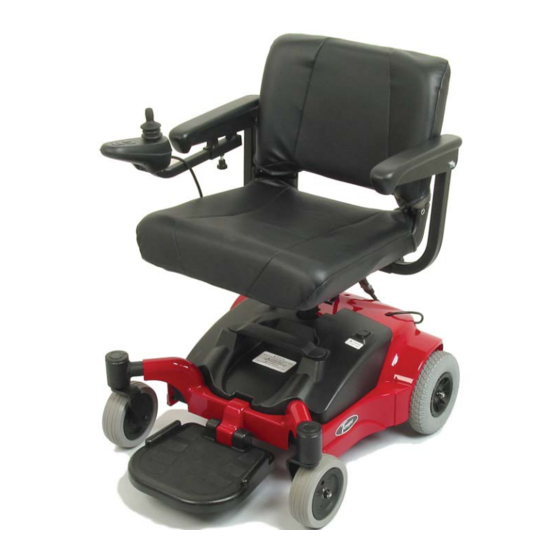
Summary of Contents for Sunrise Medical Melody
- Page 1 Quickie Melody Service Manual ©2006 Sunrise Medical Inc. 101975 Rev A...
-
Page 2: Table Of Contents
Quickie Melody Service Manual Contents Introduction ............. 0.1 Section 3 VR2 Controller ..........0.2 Understanding Controller Diagnostics Codes ... 6 Plugs/Connectors ........... 0.3 3.1 One Bar - Low Battery Voltage ....6 Basic Tool List & Main Wiring Diagram ..0.4 3.2 Two Bars - Left Motor Disconnected ...6... -
Page 3: Introduction
Service Manual. This Service Manual is intended as a troubleshooting guide for the Quickie Melody. Photo- graphs and content may differ from the actual products in some cases due to changes in specifications and other factors. -
Page 4: Vr2 Controller
Speed/Profile indicator- A se- ries of five LED’s, which display speed and profile settings Speed/ Profile Decrease. Used Speed/ Profile Increase. Used to decrease the Speed/ Profile to Increase the Speed/ Profile setting. setting. SUNRISE MEDICAL MELODY SERVICE MANUAL 2006 PAGE 0.2... -
Page 5: Plugs/Connectors
M1 = RIGHT SIDE MOTOR M2 = LEFT SIDE MOTOR JSM = JOYSTICK MODULE INH-2 = INHIBIT 2 A1 = ACTUATOR 1 A2 =ACTUATOR 2 OBC = ON BOARD CHARGER + - =BATTERY SUNRISE MEDICAL MELODY SERVICE MANUAL 2006 PAGE 0.3... -
Page 6: Basic Tool List & Main Wiring Diagram
• 5mm socket wrench Wiring Diagram for VR2 Controller Package A/C INPUT CHARGER 24v BRAKE 24v BRAKE SOLENOID SOLENOID RIGHT MOTOR LEFT MOTOR FUSE FUSE FUSE CIRCUIT BREAKER LEFT BATTERY LEFT BATTERY SUNRISE MEDICAL MELODY SERVICE MANUAL 2006 PAGE 0.4... -
Page 7: Troubleshooting: No Power
If the voltage meter reads below 12 volts, charge the batteries. Note: To find a bad battery, use a battery load tester. A1.3.1 If the voltage meter reads below 12 volts, charge the batteries. SUNRISE MEDICAL MELODY SERVICE MANUAL 2006 PAGE 1... -
Page 8: Not Charging
To make sure the fuse is not blown, set the meter to ohms and measure the resistance across the fuse. See (figure A1.4.2). If the meter reads more than one ohm, change the fuse, or else proceed to the next step.. A1.4.2 A1.4.3 SUNRISE MEDICAL MELODY SERVICE MANUAL 2006 PAGE 2... -
Page 9: Battery Connection Test
If the voltage meter reads full voltage, then replace the con- A1.5.2 troller, or else proceed to the next step. A1.5.3 If the voltage meter reads full voltage, then replace the controller. SUNRISE MEDICAL MELODY SERVICE MANUAL 2006 PAGE 3... -
Page 10: Check Battery Wire Harness
A1.8.1 If the meter reads more than 1 ohm, then change the circuit breaker. 1.9 Main Harness If the above steps did not correct the problem, change the main harness. SUNRISE MEDICAL MELODY SERVICE MANUAL 2006 PAGE 4... -
Page 11: Understanding Controller Display
This indicates a system trip, i.e. the VR2 has detected a problem somewhere in the wheelchair's electrical system. Please refer to Section 3 (VR2 Controller Diagnostics). SUNRISE MEDICAL MELODY SERVICE MANUAL 2006 PAGE 5... -
Page 12: Understanding Controller Diagnostics Codes
A3.2.2 If the meter reads between 0 to 1.5 ohms, then replace the controller. If none of the above corrects the problem, replace the left motor. SUNRISE MEDICAL MELODY SERVICE MANUAL 2006 PAGE 6... -
Page 13: Three Bars - Left Motor Wiring Trip
Test 3 Test 4 If all of the readings are open, then replace the controller. If any of the readings are short, then replace the left motor. SUNRISE MEDICAL MELODY SERVICE MANUAL 2006 PAGE 7... -
Page 14: Four Bars- Right Motor Disconnected
A3.4.2 If the meter reads between 0 and 1.5 ohms, then replace the controller. If this does not correct the problem, then replace the right motor. SUNRISE MEDICAL MELODY SERVICE MANUAL 2006 PAGE 8... -
Page 15: Five Bars - Right Motor Wiring Trip
Controller Fault - A control system trip is indicated. Make sure that all connections are secure. Check that the batteries are fully charged and in good condition, and check all joystick connections and cables. If this does not correct the prob- lem, then replace the controller. SUNRISE MEDICAL MELODY SERVICE MANUAL 2006 PAGE 9... -
Page 16: Nine Bars - Solenoid Brake Trip
3.11 Seven Bars + Speed Profile Indicator Communication Error Inspect wiring between joystick module and controller. Replace the jumper or joystick module with damaged wiring. If the problem persists replace the controller. SUNRISE MEDICAL MELODY SERVICE MANUAL 2006 PAGE 10... -
Page 17: Disassembly/Reassembly, And Adjustment
Push seat lever forward and lift off seat. (figure s1.2). Lift and remove battery case (figure s1.3). Lift "T" handle and separate front frame assembly from rear frame assembly (figure s1.4). s1.1 s1.2 s1.3 s1.5 SUNRISE MEDICAL MELODY SERVICE MANUAL 2006 PAGE 11... -
Page 18: Step 2 - Shroud Removal
Remove the rear shroud (fi g s2.2) to access motor controller. s2.2 Front shroud Remove the ten screws mounting the front shroud. (fi g s2.3) Remove the front shroud. s2.3 SUNRISE MEDICAL MELODY SERVICE MANUAL 2006 PAGE 12... -
Page 19: Step 3 - Frootrest Removal
Step 4 - Battery removal Remove the 11 screws mounting the top battery case to the bottom battery case (fi g s4.1) Remove 4 spade connectors from batteries (fi g s4.2) s4.1 s4.2 SUNRISE MEDICAL MELODY SERVICE MANUAL 2006 PAGE 13... -
Page 20: Step 5 - Motor Removal
Unplug motor from the controller (fig s5.5) Use a four mm hex key and an eight mm wrench to remove the four bolts and nuts mounting the motor to the frame (figs5.6) s5.1 s5.2 s5.3 s5.4 SUNRISE MEDICAL MELODY SERVICE MANUAL 2006 PAGE 14... -
Page 21: Step 6 - Caster Removal
Use a 19mm socket wrench to remove the caster nut (fig s7.2) s6.1 s6.2 Step 7 - Anti-tip removal Use two 10 mm wrenches to remove the bolt and nut retaining the anti-tip wheel (fig s7.1) s7.1 SUNRISE MEDICAL MELODY SERVICE MANUAL 2006 PAGE 15... -
Page 22: Step 8 - Main Wiring Harness Removal
Remove the two screws mounting battery plug to the frame (fig s8.1) s8.1 Step 9 - Rear bumper removal Use an 11mm wrench to remove the two bolts secur- ing the rear bumper to the frame (fig s5.2). s5.5 SUNRISE MEDICAL MELODY SERVICE MANUAL 2006 PAGE 16...
Need help?
Do you have a question about the Melody and is the answer not in the manual?
Questions and answers