
Related Manuals for Aim MXG Dash Logger


Summary of Contents for Aim MXG Dash Logger
- Page 1 MXG Dash Logger USER GUIDE AiM Srl. Via Cavalcanti, 8 20063 Cernusco S/N (MI) Italia Tel. (+39) 02.9290571 www.aim-sportline.com Made in Italy...
- Page 2 RPM VIA A 5 50 V SQUARE WAVE SIGNAL OR COIL 150 400 V SPEED CHANNEL Dear Customer, ANALOG INPUTS DIGITAL OUTPUTS First, we would like to thank you for choosing RACESTUDIO3 SOFTWARE. the MXG dash logger as the tool for 10.1 CONFIGURATION improving your racing-craft setup and 10.1.1 DISPLAY CONFIGURATION on-track performance.
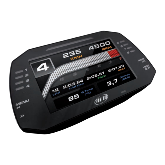
- Page 3 MXG is a color, high-contrast, so, please, don’t forget to check our choosing color, blinking frequency and high-brilliance 7”TFT dash logger web site at www.aim-sportline.com. XRK, taking advantage from GPS defining the logic for turning them on developed for race car installations.
-
Page 4: What Is In The Kit
CHAPTER 2 WHAT IS IN THE KIT 2. What is in the kit The MXG kit includes: MXG dash logger Harness GPS05 module Software... - Page 5 CHAPTER 3 LAYOUT AND PUSHBUTTONS MXG Dash Logger Configurable Alarm LEDs 1-4 Shift Lights Configurable Alarm LEDs 5-8 Motorsport Connectors Multifunctional Pushbuttons Aluminum Body...
-
Page 6: Ecu Connection
ECU. http://www.aim-sportline.com/eng/dow- 2. Read the documentation about your ECU nload/ecu-connections.htm at www.aim-sportline.com and identify the name of the proper software driver to be This list includes approximately 700 specified. different protocols and is constantly 3. - Page 7 CHAPTER 6 6. RPM The image shows an example of wiring for MXG can get the RPM signal in the following ways: the ignition system. n From ECU The output, labelled “GREY TACH” gives a n Through a square wave signal (from 5 to 50 V) 5-50V output that can be directly acquired n From the low voltage (from 150 to 400 V) from EVO4.
- Page 8 CHAPTER 7 SPEED 7. Speed 7.3 Speed Read from Wheel Sensors MXG can receive the speed signal from three different sources: MXG has four wheel speed inputs, one in n From the ECU the 37 pin connector and the other three in n From the GPS receiver included in the kit the 22 pin connector: n From the four digital channels...
-
Page 9: Analog Inputs
CHAPTER 8 ANALOG INPUTS CHAPTER 9 DIGITAL OUTPUT 8. Analog Inputs 9. Digital Output n Temperature sensors K thermocouples MXG features two digital outputs in the 22 MXG has 8 analog inputs, recorded up to Thermo-PT100 resistors pins connector. 1000 times per second each. Temperature sensors VDO Each of them can give an output of 1 amp You can connect:... -
Page 10: Racestudio3 Software
Configurations The configuration page is divided in two When you connect an AiM logger, like your n Track Manager sections. MXG, its serial number appears in the left n Analysis The left side is dedicated to the folders that side of your screen. - Page 11 CHAPTER 10 RACESTUDIO3 SOFTWARE 10.1.1 Display Configuration After selecting the OVERLAY configuration feature, the following page appears: Please don’t forget to select the proper ECU brand and model to which connect your MXG. After having entered the MXG configuration page, you can see different tabs, which are useful for selecting one of the following configuration features: n Overlay...
-
Page 12: Channels Configuration
CHAPTER 10 RACESTUDIO3 SOFTWARE 10.1.2 Channels configuration 10.1.3 ECU stream configuration Push the tab CHANNELS: With this feature, you can enable or disable the data coming from your ECU, and you can define the frequency for every channel and change their name. The channel configuration page will appear With this page you can define all the parameters for your analog inputs, speed inputs and digital RPM input. - Page 13 RACESTUDIO3 SOFTWARE Shift Lights Configuration Alarms configuration Using the configuration bar you can When you click “Add new alarm” the “Engine RPM is higher than 6000” manage, for every LED, color and RPM window shown in the above picture You can add different check lines and threshold value which will turn it on.
-
Page 14: Modify Or Delete An Existing Configuration
CHAPTER 10 RACESTUDIO3 SOFTWARE 10.2 Connect Your MXG to a PC 4) finally, you have to configure till when the alarm has to remain in evidence. When you connect your MXG to the PC, it is There are some options: automatically recognized, and on the left n Till when the condition remains ON side of the PC display appears the name of... - Page 15 CHAPTER 10 RACESTUDIO3 SOFTWARE 10.2.3. DataDownload 10.2.2 On Line View and Calibration Push “DOWNLOAD” for downloading the data recorded in your MXG. Push “LIVE MEASURE” for looking at the data coming from your MXG. You will see the information about the files recorded in the system: dimension and date/time of the file creation.
- Page 16 CHAPTER 11 11. GPS The GPS Module, included in the MXG kit, 11.1 Track Manager Feature provides the following information updated ten times per second: With Track Manager, you can update, modify, transmit and receive to and from n Position (latitude, longitude, altitude) MXG the coordinates of the finish line and n Speed split points of all the tracks where you are...
-
Page 17: Dynamic Filters
CHAPTER 11 11.2 Filters in Track Data Base Static Filters Management A static filter is activated by the button You can filter the list of tracks you need in “filter” [1]. different ways. The window shown here will appear. The filters can be static (1) that is to say, are recorded and used every time you use Track Manager, or dynamic (2) that are not saved It will allow you to select nations, the type... - Page 18 CHAPTER 11 11.3 How to Add a New Track to the PC Database The official AiM track Database is You can now select the file “.GPK” continuously growing. To update your PC containing the GPS database, you can import the new tracks: Press “Options”...
- Page 19 CHAPTER 11 11.5 How to Read, Write and Delete 11.4 How to Modify Track Data in the PC Tracks Information in MXG Database Connect your system to your PC using the USB cable. Click the icon on the side. The Track Manager screen will display two The window containing the track data will lists.
- Page 20 CHAPTER 11 CHAPTER 12 EXPANSION To transmit track information to MXG To receive track information from MXG 12. Expansion Select tracks to be submitted by clicking on Select tracks to be submitted by clicking on the square check or on the name of the the square check or on the name of the Memory Module track.
- Page 21 CHAPTER 13 MXG PINOUT 13. MXG Pinout Deutsch 37pin. Deutsch 22pin. 9-15V power in Ain5 gnd batt gnd analog can+ Exp +Vbatt +Vref +Vbatt can Ain6 can- Exp Ain7 +Vbext gnd analog Can1+ ECU +Vbatt Can1- ECU +Vref Ain8 k line ECU speed2 USB D+ USB D-...
- Page 22 10 RGB LEDs freely configurable - CAN connections - Expansion CAN connection GPS, Channel expansion, Lambda Controller, SmartyCam - ECU connections CAN, RS232 or OBDII Our web site aim-sportline.com is constantly - Digital outputs 2 1A 12v updated. - Analog inputs 8 fully configurable...
Need help?
Do you have a question about the MXG Dash Logger and is the answer not in the manual?
Questions and answers