Table of Contents
Advertisement
Quick Links
Advertisement
Table of Contents

Related Manuals for Aim MX2E


Summary of Contents for Aim MX2E
- Page 1 User Manual MX2E for Lotus Elise and Exige 2004-2020 Release 1.07...
- Page 2 5.2.2 – Shift Ligths configuration ................................34 5.2.3 – Display configuration..................................35 5.2.4 – SmartyCam configuration ................................37 5.3 – Managing a track on MX2E with Race Studio 3 5.4 – The device window 5.4.1 – Live measures page ..................................42 5.4.2 –...
- Page 3 • Wi-Fi connectivity It has an internal memory to record sampled data and comes with AiM GPS Module for Lotus that automatically gets lap times and a lot of important information very useful if using the vehicle on the track.
- Page 4 As shown in the image below GPS08 Module is to be placed in the dedicated housing of the cluster and its 5 pins Binder 712 male connector is to be connected to the corresponding female connector placed bottom left of MX2E back and labelled “EXP”.
-
Page 5: Installation
2.1 – Installation To install MX2E follow these instructions. Remove the original parts indicated in the image on the right. Remove the original cluster. - Page 6 Remove the original dashboard. Install the MX2E on the original bracket.
- Page 7 Connect MX2E to AiM cluster. Install MX2E and AiM cluster. Please note: in case the vehicle is a Lotus Elise Exige 2004-2007 with airbag MX2E needs an adapter harness (part number V02593010) to be placed between MX2E rear connector and the vehicle stock harness.
- Page 8 Re-install the original parts. 3 – MX2E Main features MX2E has two different working modes: Road and Track, both always enabled.
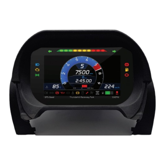
- Page 9 The two layouts for track (top images) and road (bottom images) usage are shown below. Bottom of the page an info line shows (from the left) GPS Status, track name and current time Bottom of the page an info line shows (from the left) two partial odometers and current time In paragraph 4.1.1 “Display”...
-
Page 10: Lap Times
3.1 – Lap Times MX2E calculates and shows lap times using the GPS Module included in the kit. Switching the vehicle on near a track the Module automatically recognizes it, loads start/finish coordinates and calculates lap times when these coordinates are crossed. If the track is not in the... - Page 11 • Engine problems (8) • High Beam on (9) 3.4 – The keyboard MX2E comes with a dedicated plastic cluster with integrated GPS Module that features four lateral buttons, corresponding to the logger ones • Top left: “Menu/<<” • Bottom left: “>>”...
- Page 12 4 – Menu Push MENU to enter MX2E “Preferences” and set some parameters. Please note: this is possible only if the vehicle is still. Use “PREV” and “NEXT” buttons to scroll the icons, “OK” to select the desired one and “OK” again to scroll the options. The icons stays for.
- Page 13 4.1 – Preferences Press “MENU” button and then twice “OK” button to activate “Preferences” option. Use “NEXT” and “PREV” buttons to scroll the options. When an option is selected it changes colour according to the colour set in display page (in the image below the display is set blue) Available options are: •...
- Page 14 4.1.1 – Display Once “Display” option is activated (blue in the previous image) press “OK” to enter the related page. Available options are: • Layout: Road (left image below) or track (right image below) • Theme: analog or digital • Color: blue, purple, yellow or white Selecting Track layout (right image below) two more options can be available: •...
- Page 15 As shown here below Track (left) and Road (right) layout shows different information. Number Function Track Road Engaged gear Lap Number Lap time Pred +/- Water Temperature Speed ...
- Page 16 “SELECT” button to activate model selection (left image below) • “PREV” and “NEXT” buttons to select the model year (right image below) • “OK” button to confirm; MX2E will automatically reboot Available model years are: • 2004-2007 (adapter harness part number V04000000 needed) •...
- Page 17 “CHANGE” button to set the desired reference speed between ECU or GPS speed (right image below) • “OK” button to confirm; MX2E will automatically reboot (Reference) Speed is used to compute lap times and can be :ECU or GPS. A correction factor to the shown speed is available. This last is useful to correct possible modifications of the vehicle like the use of wheels...
- Page 18 • Manual (right image below) and • Not set: does not show engaged gear on MX2E display; it allows gear calculation but does not show the value on the display Selecting “Manual” option four more options can be available: •...
- Page 19 From “Preferences” menu use “NEXT” button to scroll to “MODULES” option and press “ENTER”. Allowed modules are AIRBAG and OBDII REQ. • AIRBAG can be installed/not installed; in some cases it is removed, for example to race • OBDII REQ: enabled/disabled; OBDD request are typically diagnostics requests that add channels to the ECU protocol; they can be disabled to connect a diagnostic instrument or another device that uses the OBDII protocol Use “CHANGE”...
- Page 20 • LIGHT BUZ: enabled/disabled; it is possible to enable a buzzer that in given conditions avoid sidelights to remain on running the vehicle battery out. Given conditions are: MX2E on vehicle engine off (RPM = 0) sidelights on a vehicle door open...
- Page 21 “CHANGE”. Use “PREV” and “NEXT” button to scroll the options. Here below: on the left shift lights are linked to the engaged gear while on the right they are not. Please refer to paragraph 5.2.2 to know how to configure MX2E shift lights.
- Page 22 4.1.4 – Meas Unit From “Preferences” page Scroll to “Meas Unit” option using ”NEXT” button and press “OK”. Here it is possible to set: • Speed: km/h or mph • Temperature: Fahrenheit or Celsius 4.1.5 – Date/Time From “Preferences” page Scroll to “Date/Time” option using ”NEXT” button and press “OK”. Here it is possible to set date and time format.
- Page 23 In this page it is possible to set the track management of MX2E. Available options are “Auto” and “Manual”. Automatic: MX2E automatically recognizes the track it is running on, loads the start/finish line and the possible splits coordinates and calculates lap and split times. This is the best mode in most cases. Use: •...
-
Page 24: Reverse Camera
In Track Manager page scroll to “GPS Info” option and press “ENTER”. The page shows GPS Status with number of connected satellites and status signal as well as GPS Location with the coordinates of the place it currently is. 4.3 – Reverse Camera From “MENU”... - Page 25 From “MENU” page scroll to “Trip” option using ”NEXT” button and press “OK”. MX2E features 4 user odometers, labelled Usr 1 – Usr 4, plus a System Odometer. This last one can only be reset by an AiM or a Lotus dealer.
-
Page 26: System Info
4.5 – Wi-Fi From “MENU” page scroll to “Wi-Fi” option using ”NEXT” button and press “OK”. MX2E features a Wi-Fi module used to communicate with the PC to download sampled data after the test and to transmit/receive tracks to/from GPS Module. - Page 27 – On track application If using the vehicle on a track, for track days or competition and wish to take the maximum advantage from MX2E, an optional AiM Data Hub is needed (left image below) so to install a few sensors (suspension potentiometers, brake pressure..) and connect them to AiM Channel Expansion (right image below).
- Page 28 Using the 5 pins Binder 712 female connector labelled “EXP” rear of MX2E it is possible to connect the dash/logger to AiM Channel Expansion and LCU-One CAN. The image below shows an example of connection scheme.
-
Page 29: Connection To The Pc
5.1 – Connection to the PC AiM Race Studio 3 software configures MX2E, manages its tracks database as well as checks other device functions through the software device window (see paragraph 5.4). Connect MX2E to the PC via Wi-Fi. 5.2 – Configuration Once MX2E connected to the PC •... - Page 30 5.2.1 – CAN Expansions configuration To set a CAN Expansion: • enter “CAN Expansion” layer • press “New Expansion” button • a panel showing all available expansions shows up: select the one to add (LCU-One CAN in the example) and press “OK”. Setting LCU-One CAN To set an LCU-One CAN: •...
- Page 31 Setting Channel Expansion To set a Channel Expansion: • press “New Expansion” button; if you have already set an expansion the layer only shows the other supported expansions. • select “Channel Expansion” and press OK • name the Channel expansion and fill in its serial number or press “Get SN from a connected expansion” to receive the serial number from the connected Channel Expansion •...
- Page 32 Shift Light Module can be set as “Shift Lights and Alarm” tab (paragraph 5.2.2) or in a different way. There is no automatism in the software. Please note: for any further information about AiM CAN Expansions refer to the related user manuals available at AiM website www.aim- sportline.com documentation area, products section.
- Page 33 Removing an AiM CAN Expansion To remove an AiM CAN expansion: • activate “All” tab in “CAN Expansion” layer • right click on the expansion to remove • select “Delete Selected Expansion” option and confirm...
- Page 34 5.2.2 – Shift Ligths configuration To configure MX2E shift lights activate the related layer; this page shows up. To use the LED bar as shift lights click this icon ( ) and the setting panel shows up. Configure: • RPM value that switches the single LED on •...
-
Page 35: Display Configuration
• each box is settable through the corresponding row. Top right are all available MX2E display layout. They are labelled by an acronym (2), B_T_A in the example, whose meaning is as follows: • The first letter stays for display colour; available options are:... - Page 36 This allows to switch from one layout to the other without being obliged to reconfigure your MX2E. Moreover all channels set in the different layouts are...
-
Page 37: Smartycam Configuration
5.2.4 – SmartyCam configuration MX2E can be connected to SmartyCam HD and SmartyCam GP HD. Normally no configuration is needed but if additional sensors have been installed it is possible to see specific channels on SmartyCam video; to do so: •... - Page 38 5.3 – Managing a track on MX2E with Race Studio 3 With Track Manager function of Race Studio 3 tracks can be created, deleted and modified, transmitted and received to/from MX2E. Press “Tracks” icon. The main page is divided in three columns; on the left: •...
- Page 39 When MX2E is connected it is shown on the left bottom part of the page. Clicking on it all the tracks it contains are shown in the right column of the page. Tracks created by the user, that MXK10 calls “custom”, are labelled “User” and if the track stored in MX2E logger is different from the one stored in AiM database this is notified as shown here above.
- Page 40 Delete All: delete all tracks stored in the device memory • Save all: save all the tracks stored in the connected device; it creates a zip file that can be loaded to another AiM device • Load Saved: load the tracks previously saved in the device memory Since the software is constantly updated, may be other information or features will be available soon.
-
Page 41: The Device Window
• Download: download data stored in MX2E memory • WiFi and Properties: name the device, manage MX2E WiFi and fill in racer name, vehicle name or number, championship and venue type (generic, qualifying, test, warm up, race, test type) •... - Page 42 When the configuration has been transmitted “Live Measures” page shows ECU channels too*; as said before it is now possible to perform some operations, like start recording and make MX2E blink pressing the top right buttons (4 and 5 in the previous image).
- Page 43 Once forced the values are shown on the right of the page red boxed. Lateral “+” and “-“ buttons allows to change the values used. In the image below Fuel Alarm and Water Temperature Alarm have been forced ant the corresponding icons are red on MX2E display.
-
Page 44: Data Recall
6 – Data recall At the end of the test sampled data can be recalled pressing “MEM/OK”. First is “Today” page. Press “PAGE” Second is “Summary” page that shows all the last tests with date and place. Select the day you want to see and press “PAGE”. Third is “Day Summary”... -
Page 45: Data Download And Analysis
7 – Data download and analysis Once the test session is over it is possible to download data sampled on a PC. Connect MX2E dash logger to a PC and click on it bottom left of the software page. Once reached the device page activate “Download” layer. It shows all the information concerning the file stored in the logger: number of laps, best lap, date/time, file dimensions. -
Page 46: Wifi Configuration
1 – As an access point (AP – default) This is the ideal configuration for one only device and one only computer. In this situation MX2E creates a Wi-Fi network and works as an Access Point the PC can be connected to. - Page 47 This mode is complex and implies an external access point (AP) but it is also more flexible and powerful because allows the communication among more than one device and more than one computer in the same network. MX2E and the PC must connect to an existing Wi-Fi network made by a device that works as an external access point.
- Page 48 8.1 – Configuring MX2E dash-logger as an access point (AP) This is MX2E default configuration and is the easiest and most direct connection mode, ideal to communicate with one MX2E logger using one PC. It is free and so completely accessible by anyone. Please set an access password as soon as possible.
- Page 49 To set other parameters create a unique password to protect the device/ network. With a password the communication is safe and encrypted using WPA2-PSK standard. Characters allowed in the password are all letters, also capital, all digits and these characters: ‘+-_()[]{}$£!?^#@*\\\”=~.:;/%" “Space”...
- Page 50 Adding, for example, the driver’s name, Tom Wolf, the network name (SSID) becomes: ”AiM-MX2E-00104-Tom Wolf” Once all parameters set click “Transmit”. MX2E logger reboots and is configured with the new parameters. If MX2E logger is protected by a password, as recommended, Race Studio 3 will ask that password to authenticate.
- Page 51 8.2 – Adding MX2E loggers to an existing network This situation is ideal for a team with multiple drivers and staff members and is desired to communicate with one or more AiM devices using the same PC network. Each MX2E logger can have its password that adds another security and privacy level to the network.
- Page 52 To obtain connectivity on the device the PC has to be authenticated to the same network as shown here below. When the PC is authenticated to the network called “Network_2” it can see all devices you configured to access the same network. In the image below three AiM devices are connected to the same “Network_2” WLAN.
-
Page 53: Wi-Fi Network Settings
8.3 – Wi-Fi network settings In this chapter is a short description of how to configure a WLAN including AiM devices and a PC. Here below is an example of configuration. For better network performances we suggest the use of a network device equipped with a DHCP server and using 3x3 MIMO technology like, for example a Linksys AS3200. -
Page 54: The Internet Connectivity
192.168.0.1 – 6 8.4 – The Internet connectivity For an optimal speed of AiM device(s) it is recommended not to allow the Internet on the same network and to set the WLAN in the same way. The Internet access can of course be allowed on the network but this would degrade the communication. - Page 55 8.6 – Working on Mac with virtualized Windows Race Studio 3 only works on Windows operative systems; Mac users can use a virtualized Windows machine. The main problem is that the host OS (Mac) must share its Wi-Fi interface with the virtualized operative system (Windows) as Ethernet interface and not as Wi-Fi interface.
- Page 56 To ensure that the communication works select “Open Network preferences…” menu. Verify that the status in the window that shows up is “Connected” and that the IP address associated is, for example, 10.0.0.10 (could be 10.0.0.11, 10.0.0.12, or generically 10.0.0.x). To enable Race Studio 3 correctly working on a Mac with virtualized Windows •...
-
Page 57: Connected Device Visualization Issues
This is why we always suggest using an Wi-Fi (WLAN) router. This router works as an Access Point allowing more external devices to connect to its network. MX2E logger Wi-Fi configuration is to be... -
Page 58: New Firmware Upgrade
9 – New firmware upgrade Our technicians and engineers are constantly working to improve both the firmware (the application that manages the device) and the software (the application installed on the PC). Each time a new firmware and/or software version is available the icon here above appears with an arrow indicating that something is available for download (otherwise the icon only shows the cloud). - Page 59 10 – Rear cameras connection and management MX2E logger can manage rear cameras through the 5 pins Binder 712 female connector placed bottom right on the back of MX2E and labelled “Mirror Camera” as shown here below. The connector allows the connection of up to two analog cameras.
-
Page 60: Appendix 1 - Ecu Channels Logged By Mx2E
Appendix 1 – ECU channels logged by MX2E MX2E sample and records the channels supplied by the ECU according to the vehicle model year. Lotus Elise-Exige 2004-2007. CHANNEL NAME CHANNEL FUNCTION SAMPLING FREQUENCY Engine RPM Vehicle Speed Vehicle Speed Water_Temp... - Page 61 Lotus Elise-Exige 2011-2019. CHANNEL NAME CHANNEL FUNCTION SAMPLING FREQUENCY Engine RPM GEAR Gear Vehicle Speed Vehicle Speed Speed FL Front Left Wheel Speed Speed FR Front Right Wheel Speed Speed RL Rear Left Wheel Speed Speed RR Rear Right Wheel Speed YRS_LatAcc Lateral Acceleration YRS_YawRate...
- Page 62 ClutchPedStatus Clutch Pedal Status LTC_5_steps Lotus Traction Control - 5 steps LTC_10_steps Lotus Traction Control - 10 steps Sport_Race_Lamp Sport Race Lamp State Switches_1 Switches State ESP_ASR_Sport ESP ASR switch state ESP_ABS_ASR 1 = ABS error 2 = ABS intervention 3 = ASR error 4 = ASR intervention 5 = ASR info lamp...
-
Page 63: Appendix 2 - Mx2E Adapter Harness
Appendix 2 – MX2E Adapter harness Here below is MX2E adapter harness, needed for Lotus Elise-Exige 2004-2007 version with airbag only. Please remember models without airbag are not supported.
Need help?
Do you have a question about the MX2E and is the answer not in the manual?
Questions and answers