Table of Contents
Advertisement
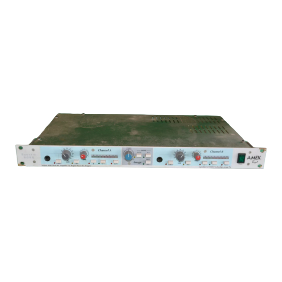
System 9098
Microphone
Serial No: A
For convenience, write your serial number in the box above and
keep this guide in a safe place. The number can be found on the
rear of the product and also on the Authentification Certificate.
This number MUST be quoted in all communications in order to
obtain technical support and spare parts from either the factory or
your dealer.
Amplifier
IMPORTANT
Dual
User
by Rupert Neve the designer
Guide
1
Advertisement
Table of Contents

Subscribe to Our Youtube Channel
Related Manuals for Harman System 9098


Summary of Contents for Harman System 9098
- Page 1 Dual System 9098 Microphone Amplifier User by Rupert Neve the designer Guide Serial No: A IMPORTANT For convenience, write your serial number in the box above and keep this guide in a safe place. The number can be found on the rear of the product and also on the Authentification Certificate.
- Page 2 All rights reserved. Parts of the design of this product may be protected by worldwide patents. AMEK is a trading division of Harman International Industries Ltd. Information contained in this manual is subject to change without notice and does not represent a commitment on the part of the vendor. AMEK shall not be liable...
- Page 3 Contents Unpacking Safety Safety symbols Earthing Changing the fuse Mains Cable 115V/230V operation Installation Location Rack mounting Power up and clicks Cleaning Audio Connections Block Diagram Operational Guide DMA Controls M-S Operation by Rupert Neve Specifications Warranty...
-
Page 4: Check List
Unpacking Check List The following items are included with the product. It is recommended that packaging materials are retained until all expected items are accounted for and found to be operating correctly. Carton Packet containing: 4 off M6 mounting screws Moulded 4 off plastic washers 1 off fuse for 110V operation. - Page 5 Safety IMPORTANT SAFETY INSTRUCTIONS Caution For your own safety and to avoid invalidation of warranty, all text marked with these Safety Symbols should be read carefully! Please keep this information! Important Caution Warning information. Hazards or unsafe Hazards or unsafe Read this before practices which can practices which can...
- Page 6 Safety WARNING - For your own safety and to avoid invalidation of the warranty please read this section carefully. Do not place the apparatus on an unstable surface. Do not insert objects through any apertures. Do not use this apparatus near water. Unplug the unit before cleaning.
-
Page 7: Mains Cable
IMPORTANT SAFETY INSTRUCTIONS Mains Cable The supplied IEC mains cable must be terminated correctly to the AC mains supply before use. Use only an approved AC plug or power distribution device. The three cores are colour coded as follows: Green/Yellow Safety Earth The Green/Yellow core in the mains Brown... - Page 8 Sécurité Précaution Pour votre sécurité et afin de ne pas interrompre la garantie il est important de lire attentivement les paragraphes marqués d'un symbole! Conserver ce document! Importante Avis Avertissement information. Dangers ou pratiques Dangers ou pratiques Priere de lire dangereuses pouvant dangereuses pouvant avant utilisation.
- Page 9 INSTRUCTIONS DE SÉCURITÉ IMPORTANTES Cable de Secteur Le cable de secteur IEC fourni doit être correctement au cable d'alimentation avant l'utilisation. Protéger le cordon d'alimentation afin d'éviter qu'il soit piétiné, écrasé ou pincé, en particulier au niveau des prises de courant, des fiches femelles et des points de sorties de l'appareil.
-
Page 10: Installation
Installation Location This product is designed and screened to minimise internal electromagnetic emissions and provide immunity to external electromagnetic fields. To reduce the risk of performance degradation due to external interference, do not site this unit close to sources of strong magnetic fields such as power supplies, power amplifiers, loudspeakers etc. -
Page 11: Audio Connections
Audio Connections Earth Link The CHASSIS GROUND post is internally connected to both the case and the safety earth. If the link is removed for technical reasons (such as earth loops), then the ANALOGUE GROUND post must be wired separately to the installation technical earth point. Audio Connections Two identical sets of 3 pin XLR connectors are provided for each mic amp channel A and B. -
Page 12: Block Diagram
Block Diagram... -
Page 13: Operational Guide
Operational Guide Overview The System 9098 Dual Mic Amplifier (DMA) contains two identical high quality signal paths that can be used as a stereo pair or two individual paths as required. When used with a stereo microphone or a "stereo" pair of microphones, the central WIDTH and M-S controls enhance the functionality and manipulation of the stereo image. - Page 14 Operational Guide Phase A phase invert button is fitted to easily correct any phase anomalies caused by difficult microphone placement or mis-wired cables. Filter The high pass filter attenuates signals below 120Hz @ 18dB/Octave. Mute The mute switch cuts the DMA output but does not affect the meter signal. Meter An eight segment lightmeter is fitted to indicate output level.
- Page 15 Output M-S The Output M-S matrix operates immediately before the output driver stages. The Output M-S switch converts conventional L-R signals into M-S format. Used in conjunction with the Input M-S matrix, M-S encoded output signals can be generated no matter which input format is used, L-R or M-S. Width When the DMA is used with a stereo signals, the Width control can be used to modify the nature of the stereo image.
- Page 16 M-S Operation Rupert Neve Two channel stereo is most often conveyed as left and right channels carrying two independent signals. These channels can create a stereo image because they do not carry exactly the same signal and any elements which are identical on both left and right will produce a central mono image.
- Page 17 Phase inverted signals are normally represented by placing a minus sign in front, so -R represents the right hand signal with phase inversion. We can therefore use a second summing amplifier to produce the S signal by adding both signals together but inverting the right hand signal in the process.
- Page 18 M-S Operation Consider both signals arriving from the front/left area. These arrive at both the cardioid and figure of eight capsules and are in phase with each other. Adding them together will produce a signal level increase. Now consider both signals arriving from the front-right area. These also arrive at both the cardioid and figure of eight capsules but are out of phase with each other.
- Page 19 Uses of M-S signals M-S signals have been in use for a long time, though not always thought of as such by audio engineers. For example, FM radio broadcasting transmits an M signal with a separate S signal which is ignored in mono receivers. M-S audio can offer a number of advantages to sound engineers.
- Page 20 Jumpers O/L indicator All jumper link information is printed on the PCB. The threshold for the O/L indicator is marked next to jumper P3. Limiter insert The optional limiter inserts, P1 and P2 must both always have jumpers fitted across pins 3/4 and 5/6.
-
Page 21: Specifications
Specifications Noise - 200R source. Figures measured with RMS rectifier, 22Hz - 22kHz filter. Equivalent input noise (66dB gain) -128dBu Output noise floor (0dB gain) -100dBu Frequency Response - measured from a 150R source driving an open circuit load. 0dB Gain 20Hz - 20kHz -0.1dB <10Hz and >110kHz... -
Page 22: Warranty
Warranty Amek is a trading division of Harman International Industries Ltd. End User means the person who first puts the equipment into regular operation. Dealer means the person other than Amek (if any) from whom the End User purchased the equipment, provided such a person is authorised for this purpose by Amek or it’s accredited...
Need help?
Do you have a question about the System 9098 and is the answer not in the manual?
Questions and answers